

Gas assisted downhole pump
a technology of gas assisted pump and downhole pump, which is applied in the direction of drilling pipe, borehole/well accessories, drilling casing, etc., can solve the problems of inefficiency of continuous gas lift system, reduced flow rate of well, and inability to install most artificial lift system in the deviated section of directional or horizontal lines
- Summary
- Abstract
- Description
- Claims
- Application Information
AI Technical Summary
Benefits of technology
Problems solved by technology
Method used
Image

Examples
Embodiment Construction
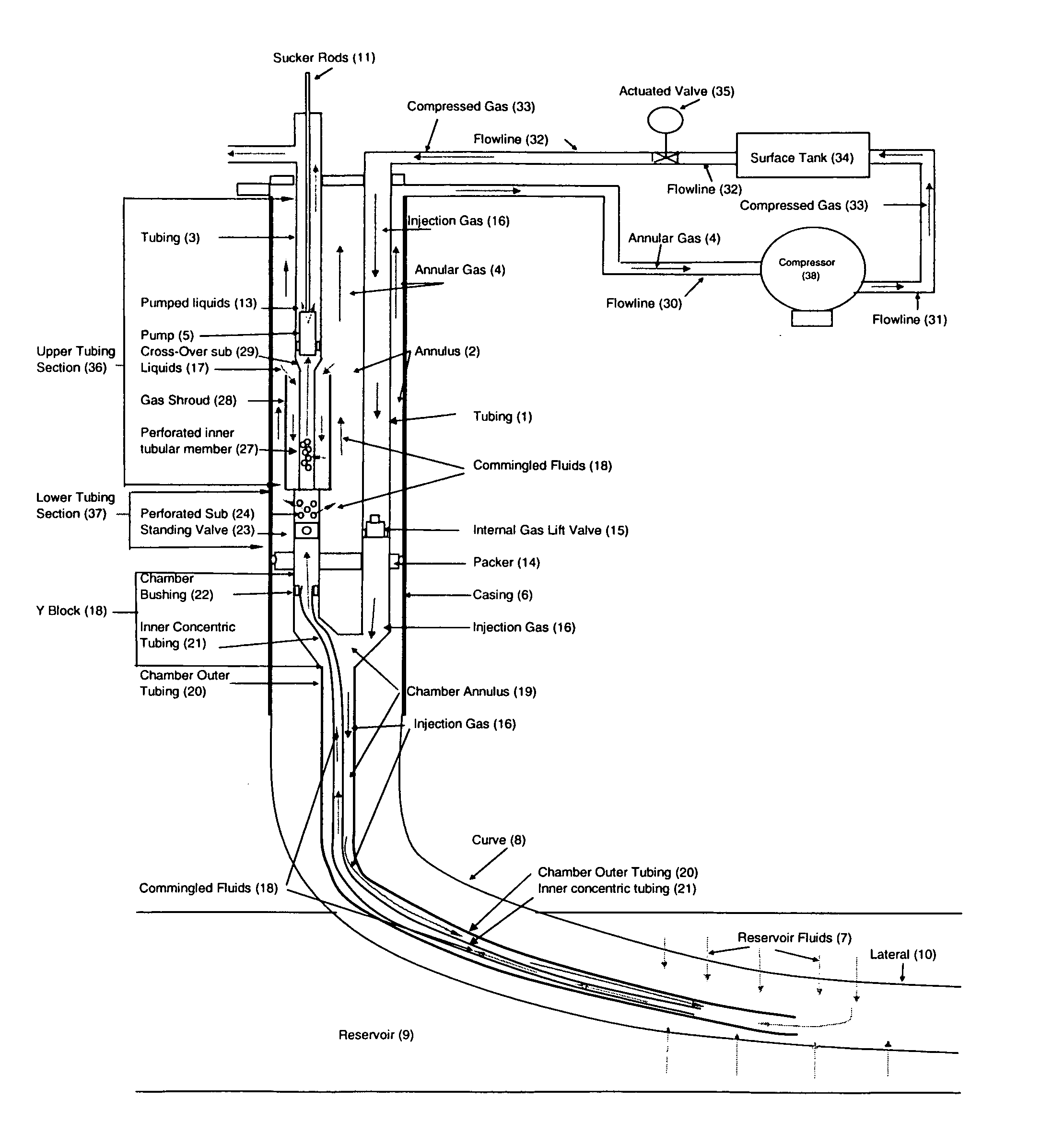
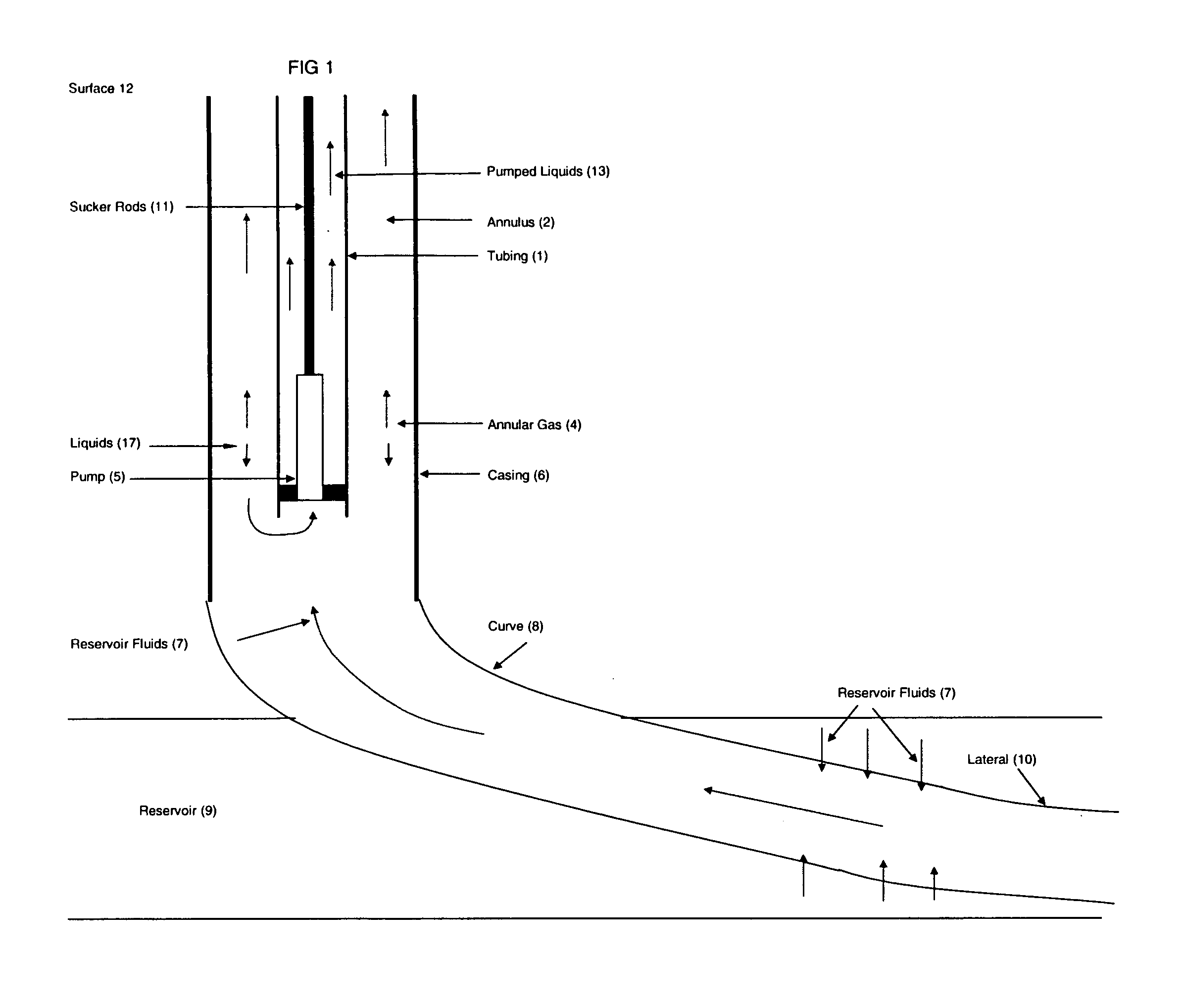
[0022]FIG. 1 shows one example of a conventional rod pump system of the prior art in a directional or horizontal wellbore. As set out in FIG. 1, tubing 1, which contains pumped liquids 13 is mounted inside a casing 6. A pump 5 is connected at the end of tubing 1 nearest the reservoir 9. Sucker rods 11 are connected from the top of pump 5 and continue vertically to the surface 12. Casing 6, cylindrical in shape, surrounds and is coaxial with tubing 1 and extends below tubing 1 and pump 5 on one end and extends vertically to surface 12 on the other end. Below casing 6 is curve 8 and lateral 10 which is drilled through reservoir 9. The process is as follows: reservoir fluids 7 are produced from reservoir 9 and enter lateral 10, rise up curve 8 and casing 6. Because reservoir fluids 7 are usually multiphase, it separates into annular gas 4 and liquids 17. Annular gas 4 emanates from reservoir fluids 7 and rises in annulus 2, which is the void space formed between tubing 1 and casing 6. ...
PUM
 Abstract
Description
Claims
Application Information