Reservoir fluids production apparatus and method

a production apparatus and fluid technology, applied in the direction of positive displacement liquid engine, piston pump, borehole/well accessories, etc., can solve the problems of restricting the flow of gas to the surface, choking off gas production completely, and restricting the flow of liquids

Inactive Publication Date: 2001-05-22
ALBERTA INNOVATES TECH FUTURES
View PDF25 Cites 44 Cited by
  • Summary
  • Abstract
  • Description
  • Claims
  • Application Information

AI Technical Summary

Problems solved by technology

If the liquids, such as water and / or oil, are not removed, the liquids tend to accumulate and fill or load up the well, which restricts the flow of the gas to the surface.
Eventually, the liquids will choke off gas production completely.
However, the requirement for small diameter tubing may significantly restrict the flow of the liquids and reduce the gas production.
As well, the gas and the liquids are typically well mixed at the surface, which may cause problems in surface production lines, such as hydrate formation or freezing.
Further, gas lift systems have been found to be unsuitable where the downhole gas pressure or the gas velocity is low and thus, the gas is unable to overcome the pressure head of the liquids to carry the liquids to the surface.
However, the introduction of the pressurized gas into the well to lift the liquids requires the use of a compressor which tends to increase both the cost and complexity of the production apparatus required.
First, the system requires a reciprocating pump at the surface.
As well, there may be some energy loss as the gas travels from the bottom of the well to the reciprocating surface pump.
Third, reciprocation of the sucker rods within the tubing string results in wearing of the tubing string and energy loss due to friction between the sucker rods and the tubing string.

Method used


Image

  • Reservoir fluids production apparatus and method
  • Reservoir fluids production apparatus and method
  • Reservoir fluids production apparatus and method

Examples


Embodiment Construction

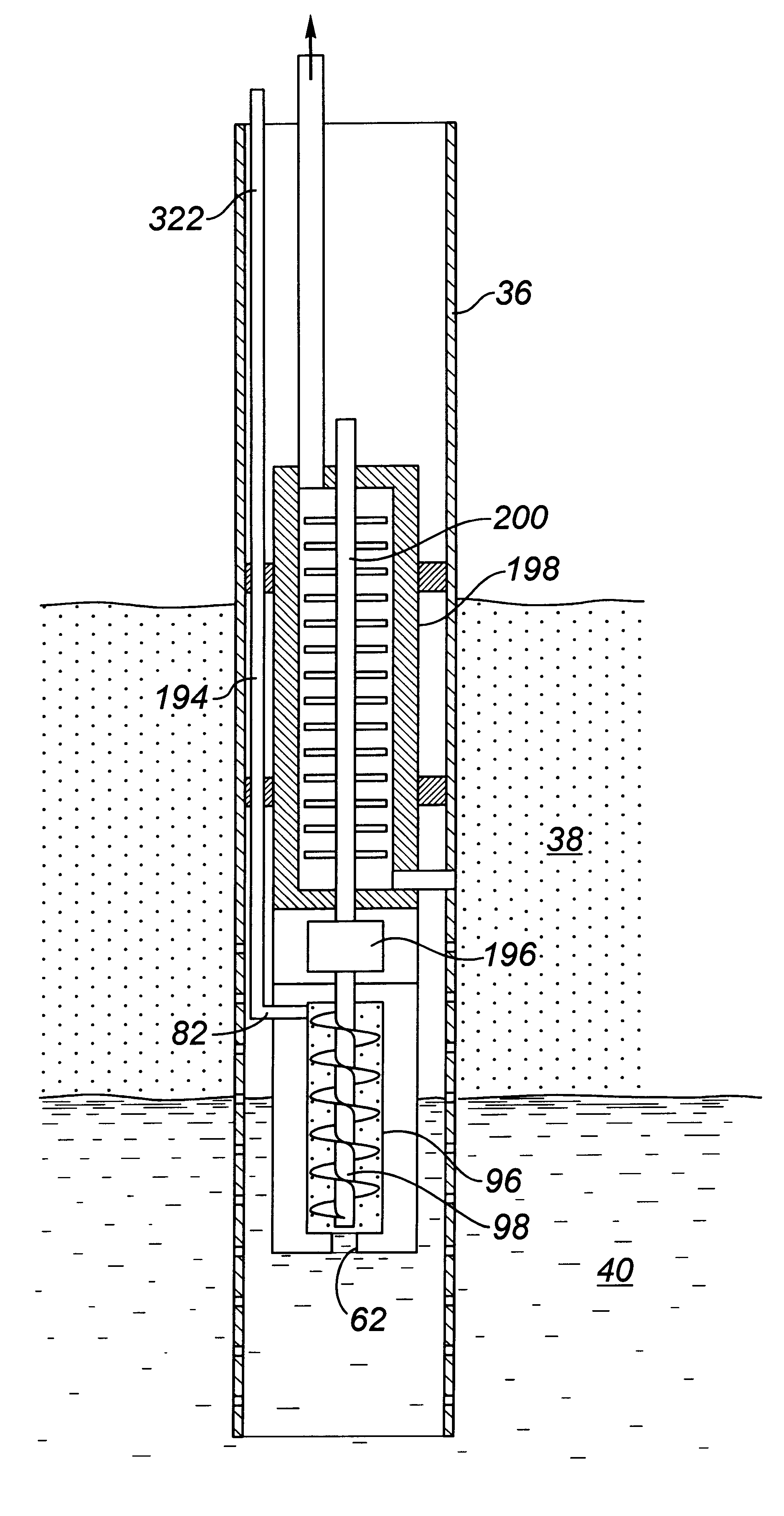
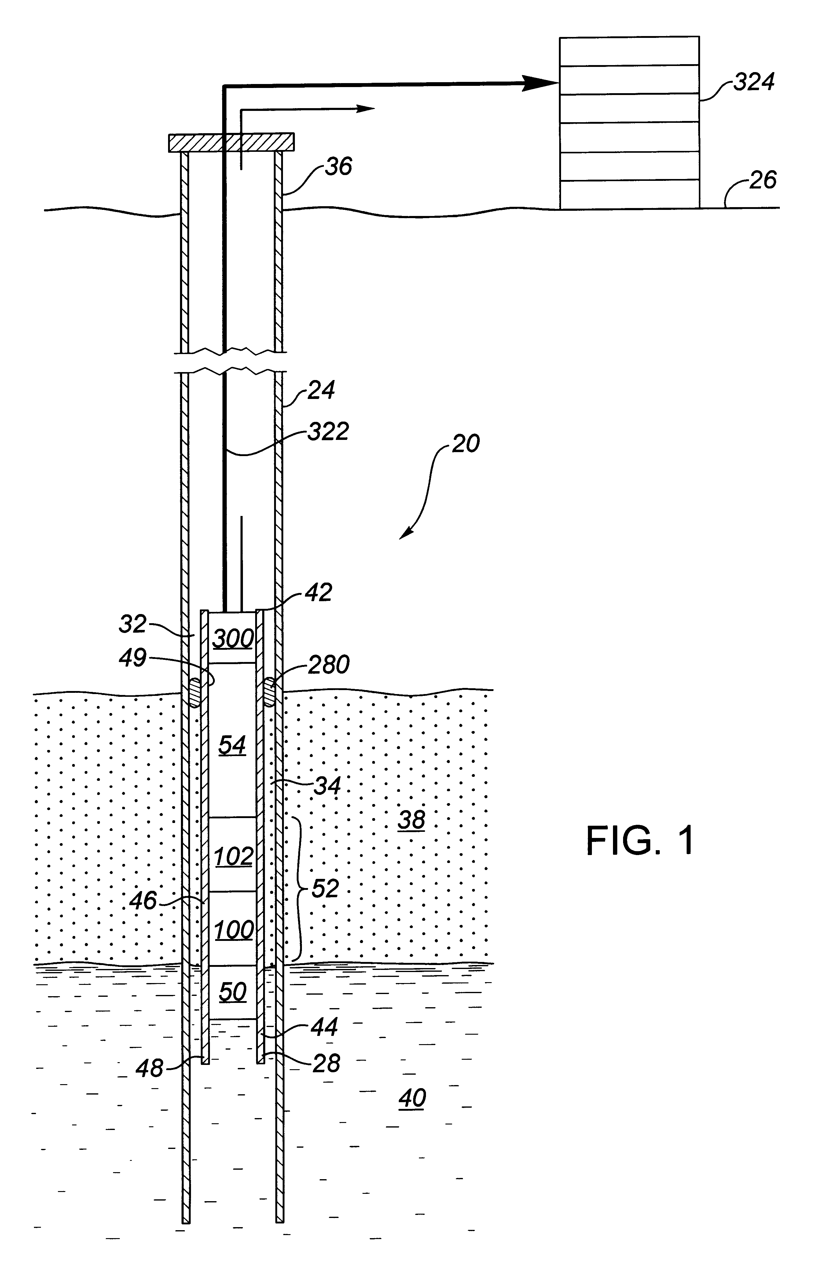
Referring to FIG. 1, the within invention is directed at an apparatus (20), and a method using the apparatus (20) for moving reservoir fluids from an underground reservoir (22) using a wellbore (24). The wellbore (24) extends from the ground surface (26) to an end (28) beneath the surface (26) and has an inner wall (30). Further, the wellbore (24) communicates with the reservoir (22) so that the reservoir fluids can enter the wellbore (24) by passing from the underground reservoir (22) into the wellbore (24). The wellbore (24) further includes an upper wellbore section (32) and a lower wellbore section (34). The lower wellbore section (34) is adjacent the end (28) of the wellbore (24) and communicates with the underground reservoir (22). The upper wellbore section (32) extends from the lower wellbore section (34) to the surface (26) and preferably does not communicate with the underground reservoir (22).

The invention is preferably used to produce reservoir fluids from an underground...


PUM


Abstract

The invention is an apparatus for moving reservoir fluids from an underground reservoir using a wellbore extending from the surface to an end beneath the surface, wherein the wellbore communicates with the reservoir such that reservoir fluids enter the wellbore and separate into a liquid phase and a gas phase at a gas pressure. The apparatus includes a first pump, for containing within the wellbore in communication with the liquid, for pumping the liquid phase. The apparatus further includes a pump drive, for containing within the wellbore, operably connected to the first pump for driving the first pump. The pump drive is powered using the gas pressure of the gas phase in the wellbore. An intake communicates with the gas phase in the wellbore and directs the gas phase to the pump drive in order to power the pump drive, while an exhaust directs the gas phase from the pump drive. Further, the invention is a method for moving reservoir fluids from an underground reservoir using a wellbore. The method includes the steps of intaking the gas phase from the wellbore into the pump drive, powering the pump drive using the gas pressure of the gas phase in the wellbore, pumping the liquid phase from the wellbore by the first pump and exhausting the gas phase from the pump drive.

Description

The present invention relates to an apparatus and a method for moving reservoir fluids, having a liquid phase and a gas phase at a gas pressure, from an underground reservoir with the use of a wellbore, using a downhole pump powered by the gas pressure of the gas phase of the reservoir fluids.The removal of liquids which accumulate in producing wells is required in order to enhance production from the well and the overall operation of the production system. In particular, liquids removal is necessary for the dewatering of gas wells and the removal of oil from wells where mixed oil and gas exists in the underground reservoir. If the liquids, such as water and / or oil, are not removed, the liquids tend to accumulate and fill or load up the well, which restricts the flow of the gas to the surface. Eventually, the liquids will choke off gas production completely. Therefore, the problem to be overcome is to remove the liquids continually to avoid their accumulation in the well.One approac...

Claims


Application Information

Patent Timeline
Patent Type & Authority Patents(United States)
IPC IPC(8): F04B7/02E21B43/12F04B47/12F04B9/00F04B9/125E21B43/38F04B7/00E21B43/34F04B47/00
CPCE21B43/121E21B43/38F04B7/0225F04B9/125F04B47/12
Inventor RIDLEY, RODNEY K.DEROCCO, MARIO
Owner ALBERTA INNOVATES TECH FUTURES
Why Eureka
Try Eureka