[0010]The solution for flowerpots is similar, except that the sensing can be done even more efficiently and even more cheaply, and also the control of the watering itself can be done more efficiently and more cheaply, by taking
advantage of certain features of flowerpots, as explained below. Therefore, the solution or flowerpots can be regarded also as a smart-home gadget, since it uses smart and cheap
automation to both save work and time and to save water.
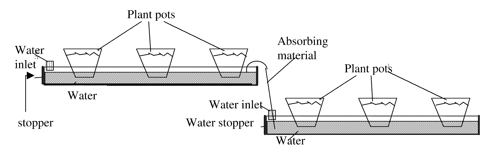
[0011]In gardens and agricultural fields preferably one or more main pipes are used with sufficient
water pressure of for example 1 or more atmospheres, and each
pipe preferably extends into smaller channels that go for example sideways, each preferably with a much lower pressure. This way, the valve that is needed to control each of these small channels needs much less force and therefore can be much cheaper than an ordinary electronic faucet. The reduced pressure can be created for example by using long twisted small conduits at or before each side-channel that easily lower the
water flow (such as for example in the pipes by Queen-Gil), which is very cheap and efficient. Another possible variation is using for example a set of preferably small water collectors that work like a
toilet's Niagara (preferably one for each side channel), or using
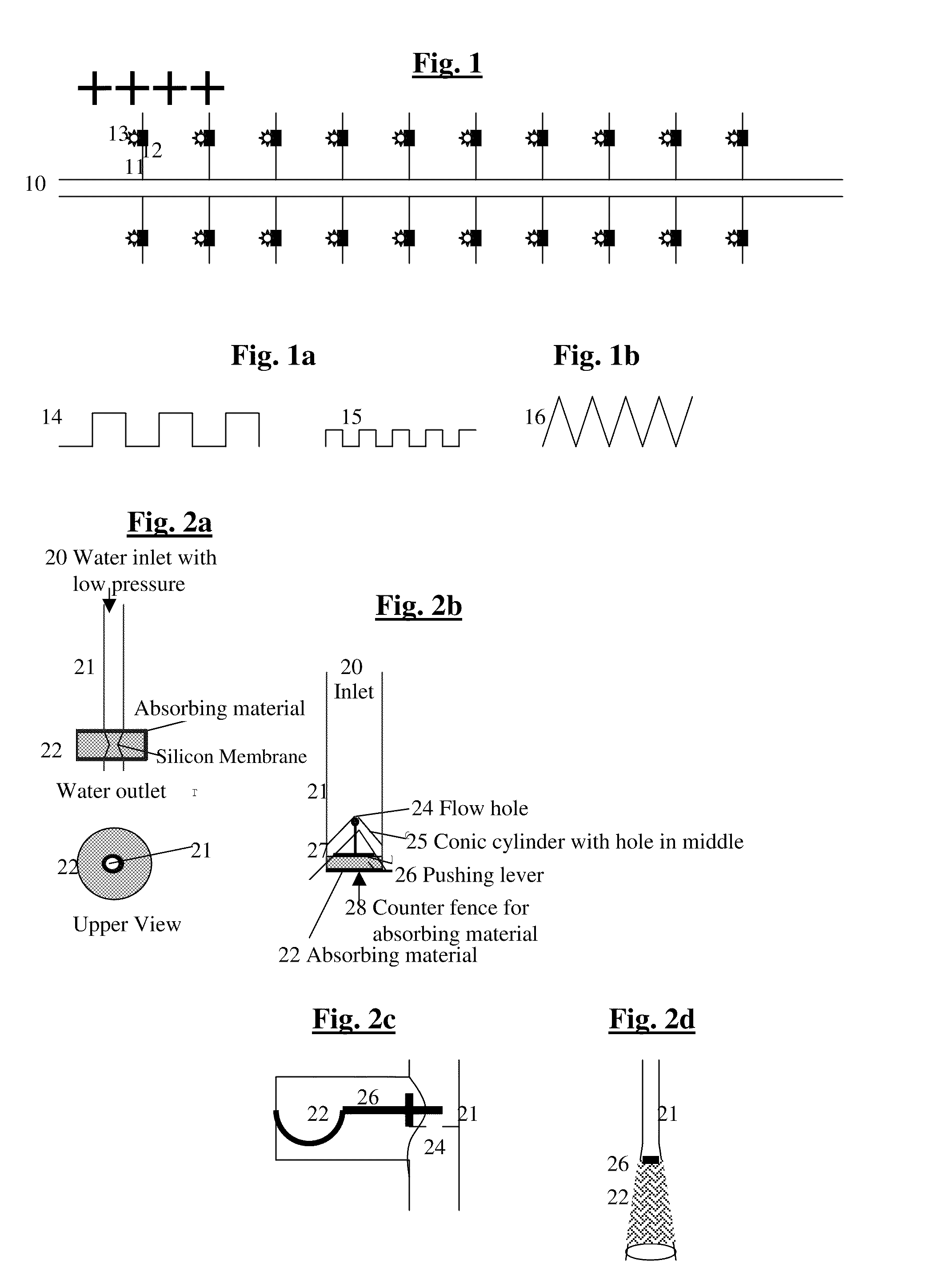
mechanical pressure reducers (however these last 2 options are less efficient). This general configuration is shown in FIGS. 1 & 1a-b. The sensing can be for example mechanical, so that for example a
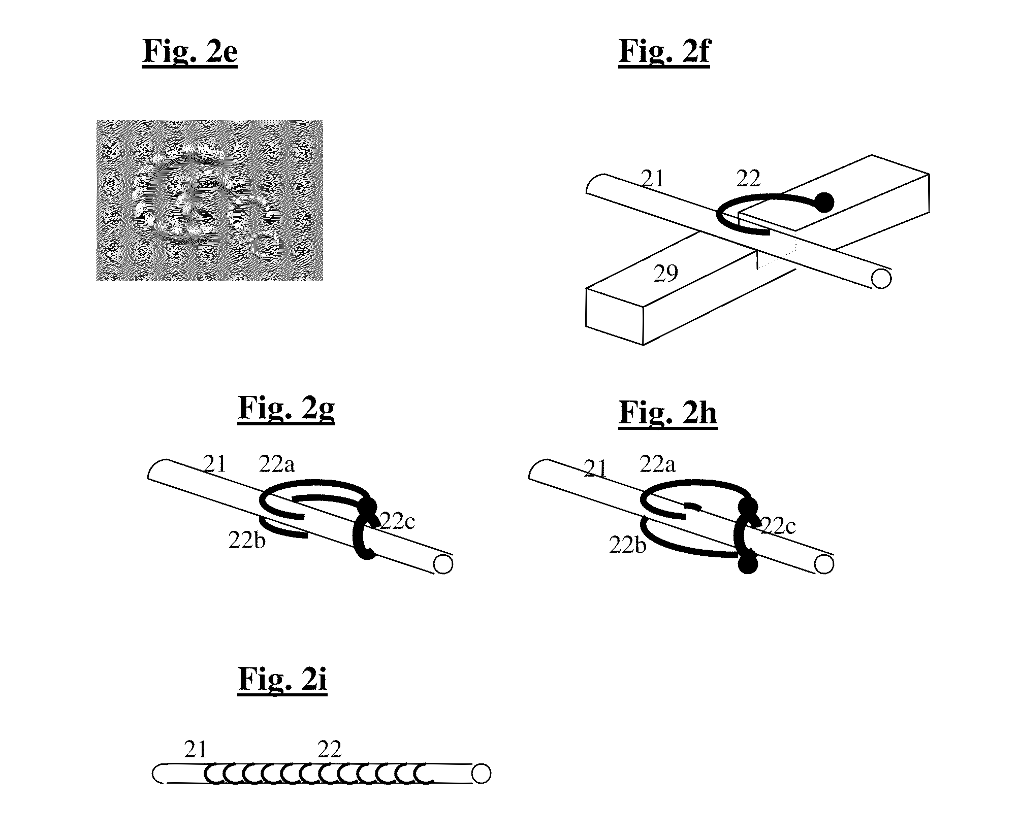
sponge or wood or hair (or other material that changes it shape when it becomes wetter or drier) closes or opens a valve or for example applies pressure to a flexible
pipe for example directly by its own mechanical change of shape or indirectly through activating an
electrical element (Preferable solutions for this are shown for example in FIGS. 2a-i). One of the most interesting of these variations is mechanical sensors based on a bi-material of two or more materials which expand differently when they become wet, thus converting the difference of the expansion into convenient movement. Or the sensing and control can be done electrically, but preferably in very cheap and efficient ways, as described below (Preferable solutions for this are shown for example FIG. 3a-d &4a-c), or the sensing and control can be based on physical and / or chemical tendencies of the water itself, preferably by using asymmetric and / or irregular and / or strong capillary material or materials, as explained above and in FIG. 6.
[0013]Another possible variation is to use similar principles like those of the solutions for the flowerpots—also for gardens and / or fields, for example by inserting (preferably more or less horizontally) a water-blocking material (such as for example a preferably strong plastic or nylon) below the plants, for example by removing 1-2 meters of earth, adding the material, and adding back the earth on top, preferably before planting the plants. The blocking material is preferably also hard enough so as not to be distorted in shape too much by the pressure from above and by the contours of land and rocks below, and preferably has also for example vertical walls around itself, so as to create one or more large
pool isolating the earth with the plants above that
pool from the rest of the earth below and around. This way, although the
humidity sensors have to work more like in the solutions described above for gardens and fields than the special solutions that can work with water dishes with flowerpots, still the usage of water can be much more efficient since the earth in the area of the plants can be kept at higher humidity levels with less water than in a normal garden or field where
excess water can always escape further below into the ground. This can work even if the blocking material does not seal the area hermetically but only significantly reduces the rate in which water can escape away downwards. Like with the
flowerpot dishes, the water blocking material can also be for example based on an array of elongated structures that look like bottom-halves of large pipes, that are inserted into the ground and covered with a layer of earth upon which for example vegetables or other agricultural products can be grown more efficiently.
[0014]Another possible variation, which can be applied in combination with any of the other variations, is to supply the plants with the same
water supply system, also with other nutrients in addition to the water, such as for example liquid fertilizers and / or minerals, and / or for example air or CO2 or
oxygen (for example by using Soda water with various degrees of CO2 melted in the water) in order to further help stimulate the
plant's growth. Such additional materials can be added for example all the time in the desired quantities as a certain percent of the water, and / or part of the time with the aid of an automatic
time schedule, and / or together with additional sensing (for example when the naturally occurring electrical potential in the earth indicates too
low salinity, or when there is indication of too little air in the ground, and / or for example depending on the level of humidity, etc.). The addition of air or CO2 or other gases is especially important, since, apart from speeding up
plant growth, it can also protect its roots from rotting, since the main cause for rotting in roots is the lack of air when they are immersed too much in water. This addition of gases such as for example air or
Oxygen or CO2 can be used also in combination with hydrophonic or hydrostatic
irrigation methods, since the main problem that limits the use of such methods to only a limited variety of plants is that in many plants the roots rot under such conditions due to lack of air. However, adding for example air or
Oxygen instead of CO2 is more preferable, since the absorption of CO2 in water makes them acidic. Since (unlike leafs) the roots need
Oxygen, adding Oxygen to the
water supply can help the
plant thrive even at levels of 100% humidity.
[0015]Another possible variation, which can be applied in combination with any of the other variations, is adding a feedback system for automatically reporting problems for example to a central
control unit, such as for example flooding or blockages. One way of accomplishing this is by allowing for example each valve or sensor at the side channels to report back the approximate amount of water passed by it and / or the percent of time it remained open and / or for example to report significant changes in conditions, such as for example suddenly finding much more humidity in a certain area, or finding that the area remains dry despite the attempts of the sensor to open the valve. (However, increase in humidity can also be caused by rain for example so this is preferably reported to the user by the central control only if it deviates significantly from other sub-areas). However this can make the system a little more expensive. Another possible variation is to use a hierarchy of more than 2 levels, so that there are not only main pipes and side channels but also one or more intermediary levels, and preferably intermediary junctures are responsible for indication and / or reporting of such problems, which is cheaper to implement, since in this case only these junctures have to be smarter. For these junctures the more preferred variation is that they simply have a cheap water-meter and report back to the center and / or to the main supply of each main
pipe the approximate amount of water consumed per time period, and / or each main pipe for example has its own water-meter and reports this, and then either the
human operator or a preferably cheap processor at the center can easily notice if there are significant deviations.

