
Dll circuit and method of controlling the same

a technology of dll circuit and lock loop, which is applied in the direction of electrical equipment, pulse automatic control, etc., can solve the problems of lengthening the access time of output data, and the limitation of how fast the locking time can becom

Active Publication Date: 2009-06-11
SK HYNIX INC
View PDF20 Cites 23 Cited by
  • Summary
  • Abstract
  • Description
  • Claims
  • Application Information

AI Technical Summary

Benefits of technology

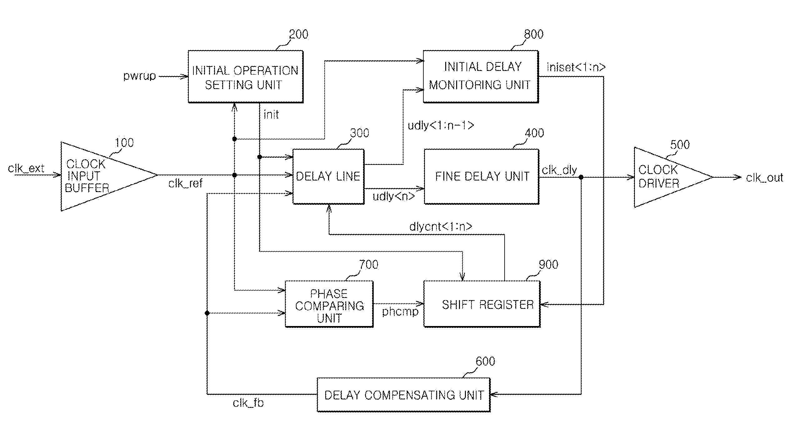
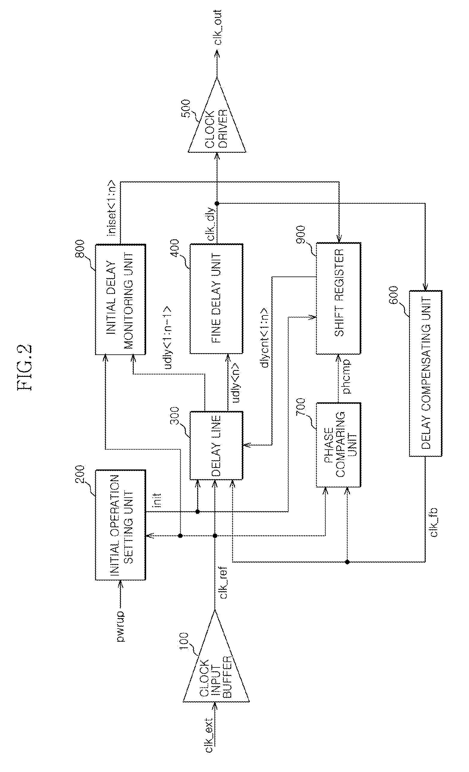
[0015]According to a further aspect, there is provided a method of controlling a delay locked loop (DLL) circuit. The method can include delaying a feedback clock signal, thereby generating a plurality of unit delay clock signals, comparing a phase of each of the plurality of unit delay clock signals and a phase of a reference clock signal, thereby generating an initial setting code, controlling a delay amount of the reference clock signal by a delay line using the initial setting code as delay control code, and generating the delay control code in response to a phase comparison signal, thereby controlling the delay amount of the reference clock signal by the delay line.

Problems solved by technology

The DLL circuit is also used to resolve the following problem: If an internal clock signal used in a semiconductor integrated circuit is delayed by a clock buffer and a transmission line, a phase difference is generated between the internal clock signal and an external clock signal, which results in lengthening an output data access time.
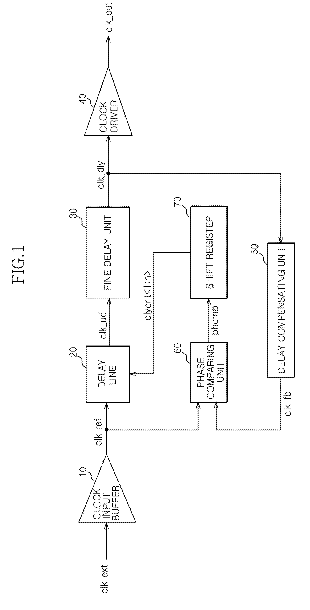
However, in a conventional DLL circuit, which uses a shift register and a delay line to perform a delay locked operation, there is a technical limitation on how fast the locking time can become.

Method used


Image

  • Dll circuit and method of controlling the same
  • Dll circuit and method of controlling the same
  • Dll circuit and method of controlling the same

Examples


Embodiment Construction

.”

BRIEF DESCRIPTION OF THE DRAWINGS

[0017]Features, aspects, and embodiments are described in conjunction with the attached drawings, in which:

[0018]FIG. 1 is a block diagram illustrating the structure of a conventional DLL circuit.

[0019]FIG. 2 is a block diagram illustrating a structure of a DLL circuit according to one embodiment.

[0020]FIG. 3A is a diagram specifically illustrating a structure of an initial operation setting unit that can be included in the circuit illustrated in FIG. 2.

[0021]FIG. 3B is a timing chart illustrating the operation of an initial operation setting unit that can be included in the circuit illustrated in FIG. 3A.

[0022]FIG. 4 is a diagram specifically illustrating a structure of a delay line that can be included in the circuit illustrated in FIG. 2.

[0023]FIG. 5 is a diagram specifically illustrating a structure of an initial delay monitoring unit that can be included in the circuit illustrated in FIG. 2.

[0024]FIG. 6 is a diagram specifically illustrating a...


PUM


Abstract

A delay locked loop (DLL) circuit includes an initial operation setting unit configured to generate an initial operation signal in response to a reference clock signal and an operation start signal; a shift register configured to generate a delay control code in response to the initial operation signal, a phase comparison signal, and an initial setting code; a delay line configured to delay the reference clock signal or a feedback clock signal in response to the initial operation signal and the delay control code, thereby generating a plurality of unit delay clock signals; and an initial delay monitoring unit configured to generate the initial setting code in response to the reference clock signal and the plurality of unit delay clock signals.

Description

CROSS-REFERENCE TO RELATED PATENT APPLICATION[0001]This application claims the benefit under 35 U.S.C 119(a) of Korean Application No. 10-2007-0127474, filed on Dec. 10, 2007, in the Korean Intellectual Property Office, the disclosure of which is incorporated herein in its entirety by reference as if set forth in full.BACKGROUND[0002]1. Technical Field[0003]The descriptions herein relate to a delay locked loop (DLL) circuit and a method of controlling the same, and more particularly, to a DLL circuit that generates an internal clock signal whose phase is more advanced than a phase of an external clock signal and a method of controlling the same.[0004]2. Related Art[0005]In general, a conventional DLL circuit is used to generate an internal clock signal whose phase is more advanced than a phase of a reference clock signal obtained by converting an external clock signal by a predetermined time. The DLL circuit is also used to resolve the following problem: If an internal clock signal ...

Claims


Application Information

Patent Timeline
Patent Type & Authority Applications(United States)
IPC IPC(8): H03L7/06
CPCH03L7/10H03L7/0814H03L7/0818H03L7/0816H03L7/06
Inventor SHIN, DONG-SUK
Owner SK HYNIX INC
Learn More