Mechanical lift maintenance indication system

a technology for maintenance indication and mechanical lifts, applied in the field of theatrical lift maintenance, can solve the problems of affecting the performance of lifts, and affecting so as to improve the safety of lifts, improve the energy efficiency and/or operability of lifts, and improve the information of lift consumers

Inactive Publication Date: 2009-06-11
J R CLANCY
View PDF10 Cites 8 Cited by
  • Summary
  • Abstract
  • Description
  • Claims
  • Application Information

AI Technical Summary

Benefits of technology

[0015](ii) encourage routine maintenance to improve energy efficiency and / or operability of lifts;
[0016](iii) improve lift consumer information by clarifying responsibility for routine maintenance and consequences of failing to perform routine lift maintenance;
[0017](iv) increase lift safety and security by limiting the ability to reset indicator(s) to certain individuals (for example, individuals having special tools needed to open the indicator housing); and / or
[0018](v) encourage lift maintenance, and thereby enhance lift efficiency and safety, by limiting operation of the lift until a lift maintenance technician performs routine maintenance required due to passage of a predetermined amount of time and / or lift usage.

Problems solved by technology

When the maintenance detection module detects that lift maintenance should be performed, the lift performance limiting module limits performance of the lift in some way.
There are many ways that lift performance should be limited.
In some preferred embodiments the lift performance limiting module progressively limits lift performance more and more with continued lift usage after it has been determined that maintenance is required—in this way, the degree of limitation of lift performance will be correlated with the urgency of the need for lift maintenance.

Method used


Image

  • Mechanical lift maintenance indication system
  • Mechanical lift maintenance indication system
  • Mechanical lift maintenance indication system

Examples


Embodiment Construction

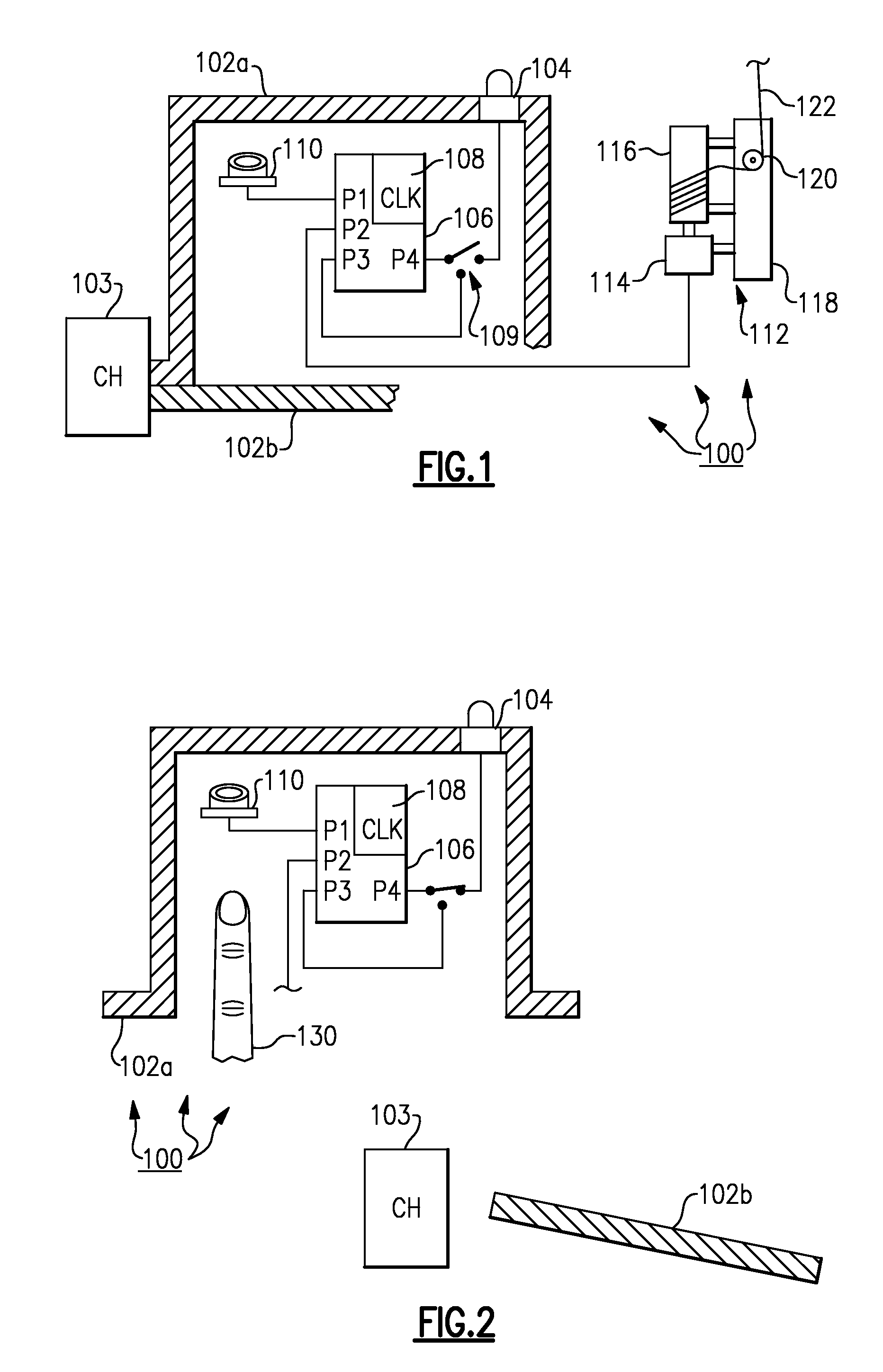
[0024]As shown in FIGS. 1 and 2 theatrical lift system 100 according to the present invention includes: controller housing 102; connection hardware 103; indicator LED 104; controller programmable logic circuitry 106; light on / off switch 109; timer reset 110; lift motor and gear train 114; drum 116; frame 118; head sheave 120 and cable 122. Circuitry 106 includes: ports P1, P2, P3, P4; and timer circuitry portion 108. The timer is programmed to measure a predetermined time interval. During this time interval: (i) light on / off switch 109 remains in the off position so that LED 104 remains off; (ii) circuitry 106 provides electronic control of the mechanical lift components 114, 116, 120, 122 through port P2; and (iii) routine maintenance is not yet required. After the predetermined interval of time passes: (i) circuitry 106 causes an appropriate signal to go out over P3 to close light on / off switch 109; and (ii) when light on / off switch closes, LED 104 receives power and goes on.

[0025...


PUM


Abstract

A theatrical lift including a timer and an indicator light. The light indicates a need for maintenance after a predetermined amount of time passes as measured by the timer. Also, a lift, such as a theatrical lift, including an indicator, a reset switch and an indicator housing. The indicator is located on the indicator housing. The reset switch is located inside of the indicator housing. The indicator housing can be opened or partially opened to allow selective access to the reset switch. In this way, the reset switch can be easily reset by a lift maintenance technician as part of performing routine maintenance on the lift, but will not be easily reset by a lift operator as a casual matter.

Description

RELATED APPLICATION[0001]The present application claims priority to U.S. provisional patent application No. 60 / 992,861, filed on Dec. 6, 2007; all of the foregoing patent-related document(s) are hereby incorporated by reference herein in their respective entirety(ies).BACKGROUND OF THE INVENTION[0002]1. Field of the Invention[0003]The present invention relates to theatrical lifts (see DEFINITIONS section) and more particularly to maintenance of theatrical lifts.[0004]2. Description of the Related Art[0005]Mechanical lifts, winches and the like are conventional. Older designs were generally human powered and counterweight assisted. More recent designs are generally motorized. It is conventionally recognized that these devices require maintenance, including both routine periodic maintenance, and non-routine maintenance upon observance of a fault condition. As an example, of routine maintenance, certain lift components may be recommended to be checked by professional at predetermined t...

Claims


Application Information

Patent Timeline
Patent Type & Authority Applications(United States)
IPC IPC(8): G08B21/00
CPCA63J1/028B66D1/54
Inventor ESCHELBACHER, LAWRENCEMURPHY, MICHAELTHEIS, JR., ROBERT J.
Owner J R CLANCY
Why Eureka
Try Eureka