Antenna Module-Use Magnetic Core Member, Antenna Module, and Portable Information Terminal Having the Same

a technology of antenna modules and magnetic cores, applied in loop antennas with ferromagnetic cores, cores/yokes, instruments, etc., can solve the problems of increasing the thickness of the antenna module, lowering the ic read voltage and a short communication distance, and eddy current loss, so as to avoid the influence of natural resonance of ferrite material in an applied frequency band, stable communication characteristics, and the effect of thinning the antenna modul

Inactive Publication Date: 2009-06-11
SONY CORP
View PDF3 Cites 97 Cited by
  • Summary
  • Abstract
  • Description
  • Claims
  • Application Information

AI Technical Summary

Benefits of technology

[0011]In order to reduce an eddy current loss while maintaining high a permeability of a magnetic core member, almost all conventional cases take a measure of limiting a large particle size of magnetic powders and reducing an absolute amount (mixture ratio) of magnetic powders to be mixed.
[0031]By manufacturing an antenna module by using the magnetic core member having the above-described structure, a thickness of the magnetic core member can be suppressed to 1 mm or thinner while a communication distance of 100 mm or longer is ensured in the state that the antenna module is accommodated in a housing of, e.g., a portable information terminal. Thinning the antenna module can be realized easily.

Problems solved by technology

However, as the particle size of magnetic powders is made large, a power loss due to an eddy current loss in the magnetic core member becomes considerable, resulting in a lowered IC read voltage and a short communication distance.
This is an eddy current loss.
This results in increasing the thickness of an antenna module.

Method used


Image

  • Antenna Module-Use Magnetic Core Member, Antenna Module, and Portable Information Terminal Having the Same
  • Antenna Module-Use Magnetic Core Member, Antenna Module, and Portable Information Terminal Having the Same
  • Antenna Module-Use Magnetic Core Member, Antenna Module, and Portable Information Terminal Having the Same

Examples


first example

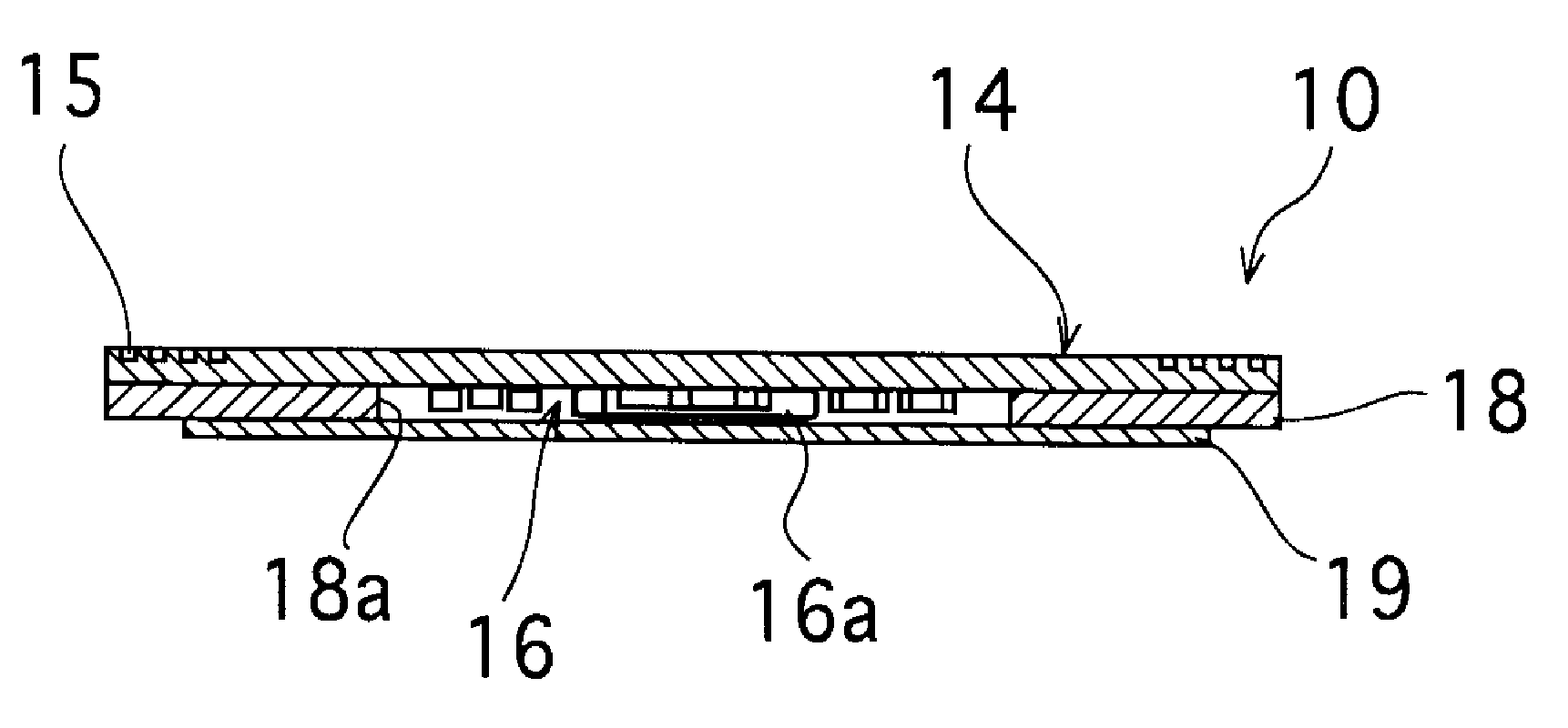
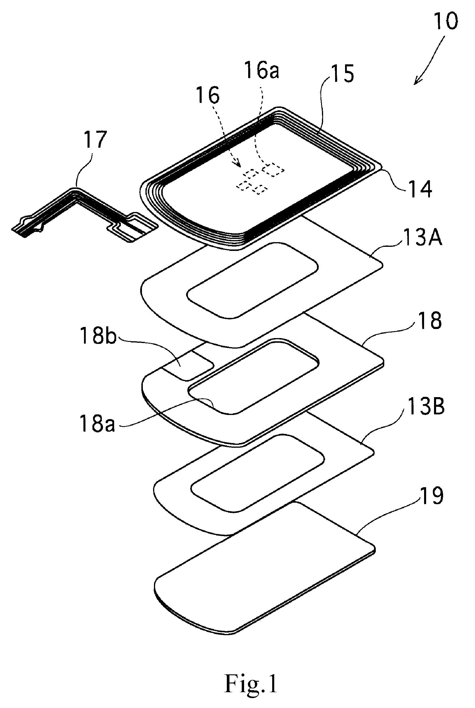
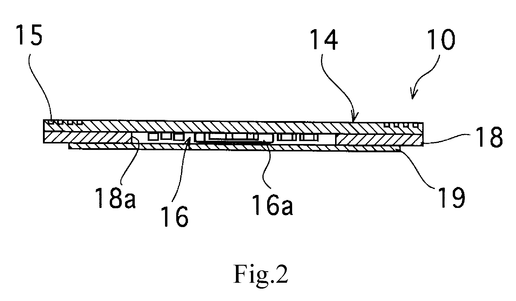
[0085]Antenna modules 10 having the structure shown in FIG. 1 were manufactured by preparing a plurality of samples of the magnetic core member made of a composite material having different types or mixture ratios of magnetic powders, a reciprocal Q of the loss factor and a performance index (Q×μ′) were calculated on the basis of μ′ and μ″ at the time of applying a high frequency magnetic field (13.56 MHz), and communication distances (communication distances in the antenna module state assembled in a portable information terminal) were evaluated. “Nylon 12” (trade name) was used as a binder. Experiment results are shown in FIG. 11 and Table 1.

TABLE 1SAMPLE-1SAMPLE-2SAMPLE-3SAMPLE-4SAMPLE-5SAMPLE-6SAMPLE-7Fe—Si—AlFe—Si—CrFe—Si—AlFe—Si—AlFe—Si—CrAmorphousFerriteMagnetic Coreμ′ (H / m)30506077455050Characteristicsμ″ (H / m)591217110.3Q65.654.54550166.7μ′× Q180278300349202525008333AntennaCommunication92.698.2103.5104.5114.2115120CharacteristicsDistance (mm)Coil3.64.34.54.44.34.34.3Inductan...

second example

[0093]Antenna modules 10 shown in FIG. 1 were manufactured by preparing a plurality of samples of the magnetic core member made of sintered ferrite containing Ni—Zn—Cu and having different material compositions, the reciprocal Q of the loss factor and the performance index (Q×μ′) were calculated on the basis of μ′ and μ″ at the time of applying a high frequency magnetic field (13.56 MHz), and communication distances (communication distances in the antenna module state assembled in a portable information terminal) were evaluated. Experiment results are shown in Table 2.

TABLE 2SAMPLE ASAMPLE BSAMPLE CSAMPLE-5FerriteFerriteFerriteFe—Si—CrMagnetic Coreμ′65422045Characteristicsμ″170.30.11μ′× Q250580040002025AntennaCommunication105.6122.0114.5114.2CharacteristicsDistance (mm)Coil4.54.33.54.3InductanceL(μH)Coil10.78.06.310.1Resistance(Ω)

[0094]Samples A to C were formed at three points in the composition diagram of a ferrite material containing Ni—Zn—Cu shown in FIG. 8: 48Fe2O3-15NiO-28ZnO-...


PUM

PropertyMeasurementUnit
communication distanceaaaaaaaaaa
thicknessaaaaaaaaaa
thicknessaaaaaaaaaa

Abstract

There are provided an antenna module-use magnetic core member, an antenna module and a portable information terminal provided with the same, capable of improving a communication distance without increasing a module thickness. In an antenna module (1) in which a sheet-formed magnetic core member (4) is stacked on an antenna substrate (2) on which a looped antenna is formed, one having a performance index, expressed by μ′×Q, of 300 or higher when Q is a reciprocal of a loss factor (tan δ=μ″ / μ′) expressed by a real part μ′ and an imaginary part μ″ of a complex permeability at an applied frequency is used as the magnetic core member (4).

Description

TECHNICAL FIELD[0001]The present invention relates to a antenna module-use magnetic core member suitable for use with a contactless IC tag and the like utilizing RFID (Radio Frequency identification) technologies, an antenna module, and a portable information terminal equipped with the antenna module.BACKGROUND ART[0002]Conventionally, known as a contactless IC card and identification tag (hereinafter these are collectively called a “contactless IC tag”) utilizing RFID technologies are those having an information recording IC chip and a resonance capacitor electrically connected to an antenna coil. The contactless IC tag is configured as follows. Radio waves at a predetermined frequency are transmitted from a transmission / reception antenna of a reader / writer to the antenna coil to activate the contactless IC tag, and the contactless IC tag is identified or monitored by reading information recorded in the IC chip in response to a read command on radio wave data communication or by ju...

Claims


Application Information

Patent Timeline
Patent Type & Authority Applications(United States)
IPC IPC(8): H01Q1/00H01F3/00G06K19/07H01F1/34G06K19/077H01F1/37H01F17/04H01Q1/24H01Q7/06
CPCH01Q7/06H01Q1/243H01Q7/08H01Q1/24
Inventor AKIHO, HIRAKUTAKAHASHI, ISAOSUGAWARA, TOSHIAKIYOKOTA, TOSHIAKI
Owner SONY CORP
Why Eureka
Try Eureka