Eyewear with radiation detection system

a radiation detection and eyewear technology, applied in the field of eyewear with radiation detection system, can solve the problems of corneal dystrophies, inconvenient monitoring of radiation exposure, and inability to monitor radiation exposure, so as to achieve the effect of easy monitoring of radiation exposur

Active Publication Date: 2009-06-11
INGENIOSPEC
View PDF37 Cites 74 Cited by
  • Summary
  • Abstract
  • Description
  • Claims
  • Application Information

AI Technical Summary

Benefits of technology

[0005]In one embodiment, the invention pertains to eyewear having radiation monitoring capability. Radiation, such as ultraviolet (UV) radiation, infrared (IR) radiation or light, can be measured by a detector. The measured radiation can then be used in providing radiation-related information to a user of the eyewear. Advantageously, the user of the eyewear is able to easily monitor their exposure to radiation.
[0010]As eyewear, another embodiment of the invention can, for example, include at least: a frame including at least a first temple and a second temple; a radiation detector for sensing an amount of radiation; and an electronic circuit operatively connected to the radiation detector. The electronic circuit provides at least radiation information based on at least the amount of radiation sensed by the radiation detector. The radiation detector includes at least an optical filter for reducing passage of predetermined undesired radiation therethrough, and a photodetector for sensing at least a portion of radiation that passes through the optical filter. The photodetector and the electronic circuit are internal to the frame. Further, the frame has an opening adjacent the optical filter to allow at least a portion of the radiation that passes through the optical filter to impinge on the photodetector.

Problems solved by technology

Often excessive exposure to radiation can be hazardous to one's health.
However, UV-A has also been found to play some role in skin cancer and is the cause of eye cataracts, solar retinitis, and corneal dystrophies.
Although several UV radiation measuring and warning instruments have been developed and made commercially available, these instruments are disadvantageous for various reasons.
One disadvantage is that the instruments are often a stand alone, special purpose device.
As a result, a user must separately wear the special purpose device, which can be intrusive and often inconvenient.
Another disadvantage is that those instruments, even if separate but attachable to other devices, hinder or impede the design for the devices.

Method used


Image

  • Eyewear with radiation detection system
  • Eyewear with radiation detection system
  • Eyewear with radiation detection system

Examples


Embodiment Construction

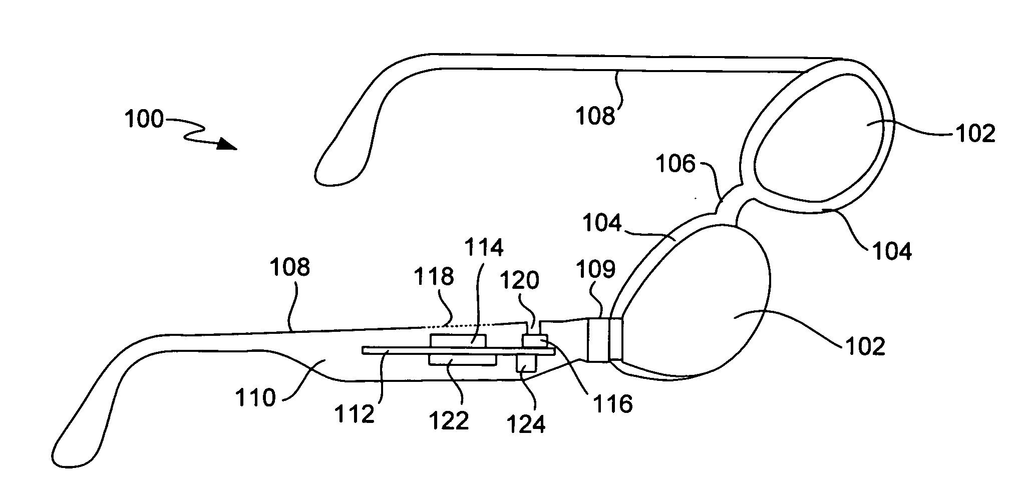
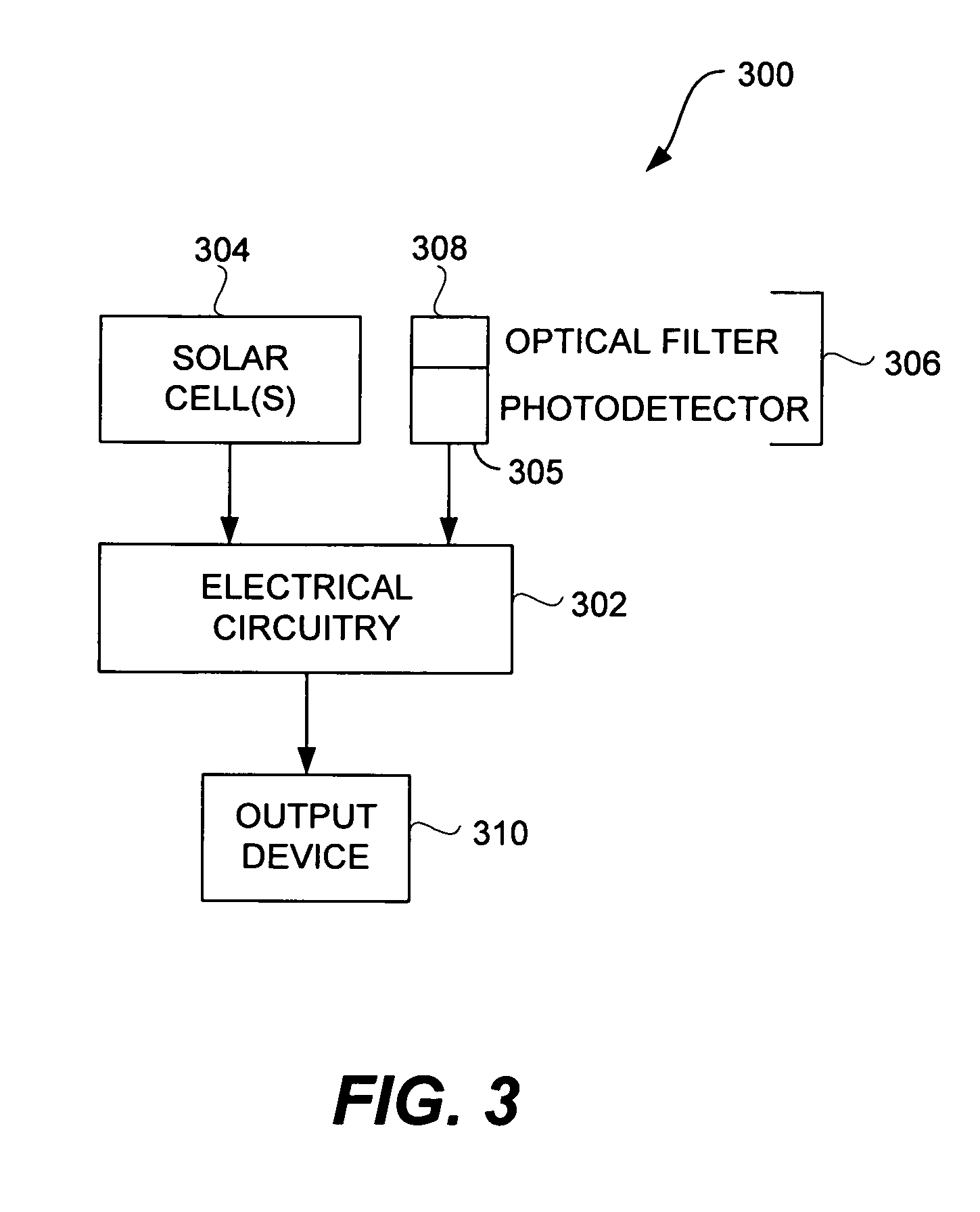
[0066]In one embodiment, an electronic circuit having radiation monitoring capability. Radiation, such as ultraviolet (UV) radiation, infrared (IR) radiation or light, can be measured by the electronic circuit. The measured radiation can then be used in providing radiation-related information to a user of the electronic circuit.

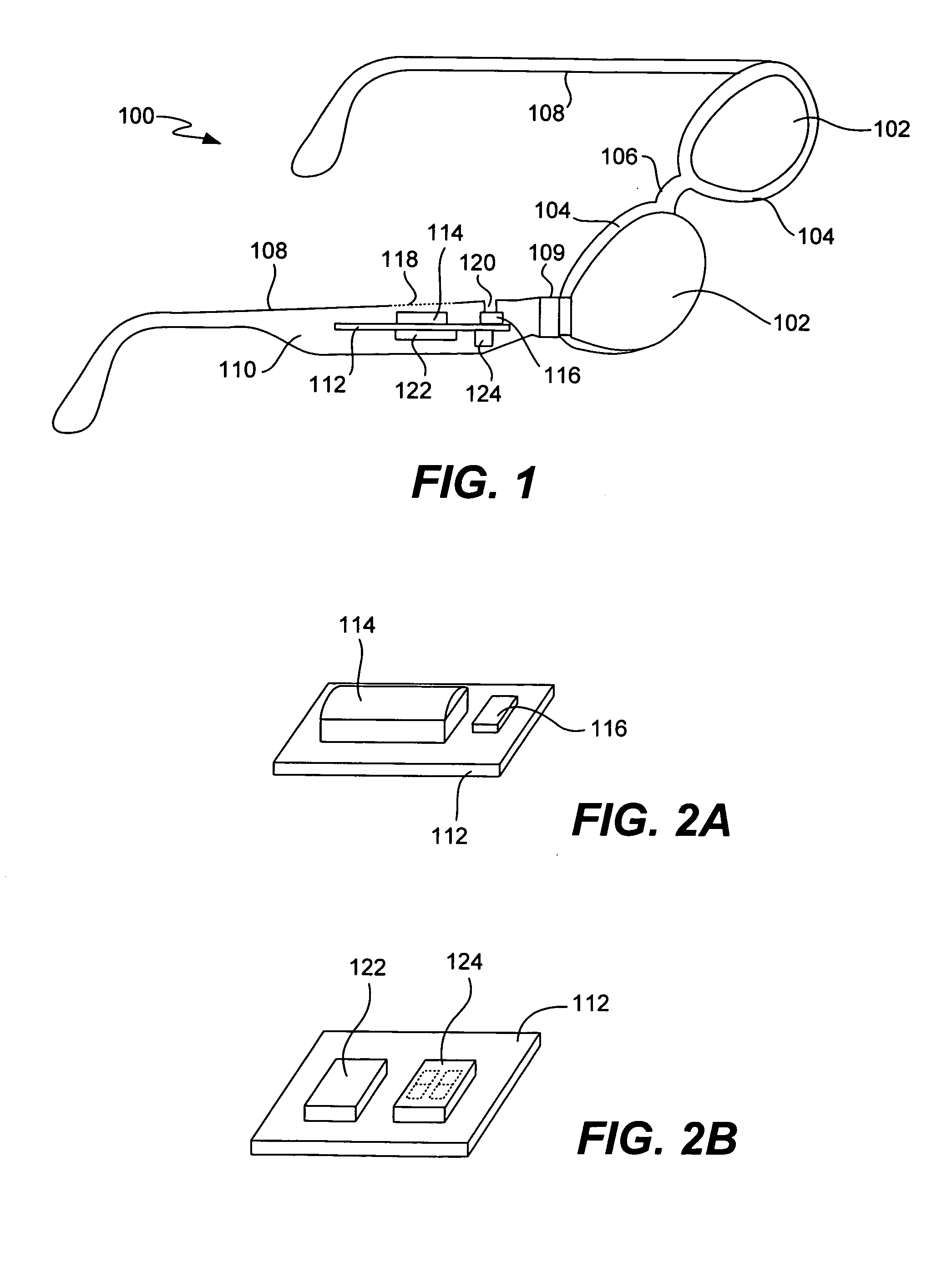
[0067]In one embodiment, all components for monitoring radiation can be integrated with eyewear, such as a frame (e.g., a temple of the frame) of the eyewear. Since any of the components provided can be integrated with the eyewear, the disturbance to design features of the eyewear can be reduced. As an example, the eyewear normally includes a pair of temples, and the components for monitoring radiation can be embedded within one or both of the temples. In one implementation, all components for monitoring radiation are integrated into a temple of the frame of the eyewear. As an example, these components can be formed together on a substrate as a module.

[0068]I...


PUM


Abstract

Eyewear having radiation monitoring capability is disclosed. Radiation, such as ultraviolet (UV) radiation, infrared (IR) radiation or light, can be measured by a detector. The measured radiation can then be used in providing radiation-related information to a user of the eyewear. Advantageously, the user of the eyewear is able to easily monitor their exposure to radiation.

Description

CROSS-REFERENCE TO RELATED APPLICATIONS[0001]This application is a continuation application of U.S. patent application Ser. No. 11 / 078,855, filed Mar. 11, 2005, entitled “EYEWEAR WITH RADIATION DETECTION SYSTEM”, which claims priority to: (i) U.S. Provisional Patent Application No. 60 / 562,798, filed Apr. 15, 2004, entitled “EYEWEAR WITH ULTRAVIOLET DETECTION SYSTEM,” and which is hereby incorporated herein by reference; (ii) U.S. Provisional Patent Application No. 60 / 583,169, filed Jun. 26, 2004, entitled “ELECTRICAL COMPONENTS FOR USE WITH EYEWEAR, AND METHODS THEREFOR,” and which is hereby incorporated herein by reference; (iii) U.S. Provisional Patent Application No. 60 / 592,045, filed Jul. 28, 2004, entitled “EYEGLASSES WITH A CLOCK OR OTHER ELECTRICAL COMPONENT,” and which is hereby incorporated herein by reference; (iv) U.S. Provisional Patent Application No. 60 / 605,191, filed Aug. 28, 2004, entitled “ELECTRICAL COMPONENTS FOR USE WITH EYEWEAR, AND METHODS THEREFOR,” and which ...

Claims


Application Information

Patent Timeline
Patent Type & Authority Applications(United States)
IPC IPC(8): G02C11/00G01J1/42G01J1/44G08B5/36
CPCG02C11/00G01J1/0238G01J1/0271G02C11/10G01J1/44G01J2001/0257G02C5/001G01J1/429A61B5/746
Inventor HOWELL, THOMAS A.CHAO, DAVIDTHOMAS, C. DOUGLASSTONG, PETER P.
Owner INGENIOSPEC
Why Eureka
Try Eureka