Sound input device

a sound input and input technology, applied in the direction of transducer casings/cabinets/supports, electrical transducers, instruments, etc., can solve the problems of nagging sound quality or unnatural audible effects

Active Publication Date: 2009-06-11
ONPA TECH
View PDF5 Cites 22 Cited by
  • Summary
  • Abstract
  • Description
  • Claims
  • Application Information

AI Technical Summary

Benefits of technology

[0009]It is therefore one advantageous aspect of the invention to provide a sound input device that o

Problems solved by technology

However, the use environment of a sound input device may include sounds except the target voice such as background noise.
The high-fr

Method used


Image

  • Sound input device
  • Sound input device
  • Sound input device

Examples


Embodiment Construction

[0053]Embodiments to which the invention is applied will be described referring to figures. Note that the invention is not limited to the embodiments described below. The invention includes any combination of the following embodiments.

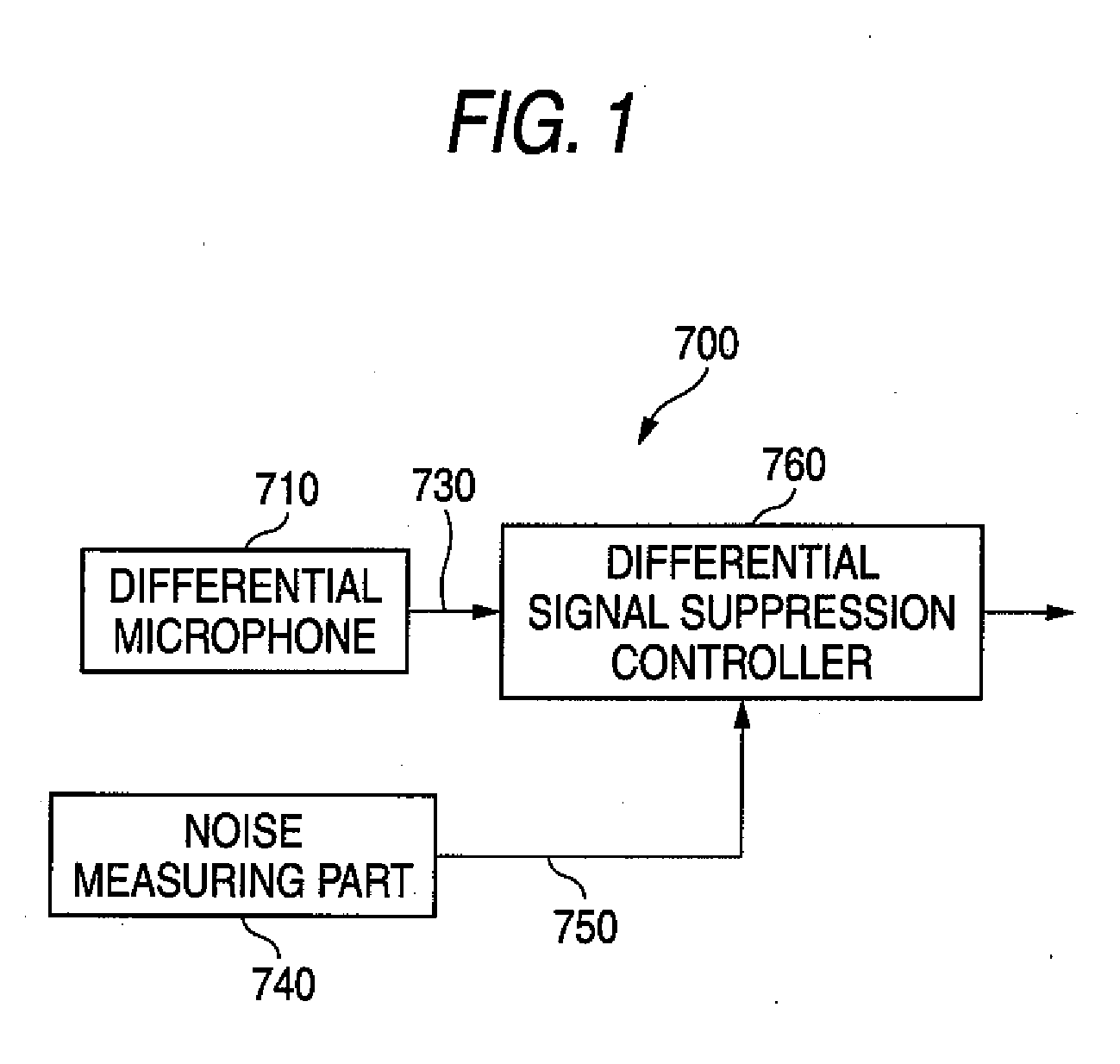
[0054]FIG. 1 illustrates the configuration of a sound input device according to this embodiment.

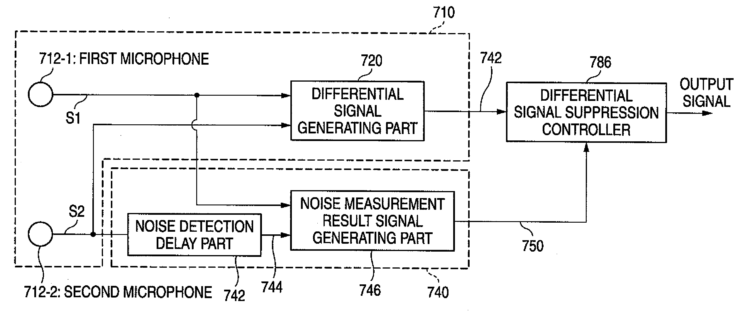
[0055]A sound input device 700 according to this embodiment includes a differential microphone 710. The differential microphone 710 generates and outputs a differential signal 730 based on a sound signal inputted to two sound receiving parts. The differential signal may be generated based on input signals from a plurality of microphones or based on the difference in the sound pressures inputted to the front surface and rear surface of a vibrating membrane by a single microphone.

[0056]The sound input device 700 according to this embodiment includes a noise measuring part 740. The noise measuring part 740 measures the noise around the differential microphone a...


PUM


Abstract

A sound input device includes a differential microphone, configured to receive sound including noise, and generate a first signal in accordance with the sound; a detector, configured to detect the noise, and generate a second signal in accordance with the detected noise; and a controller, configured to control at least one of suppression of high-frequency components of the first signal and changing of a frequency band to be suppressed of the first signal based on the second signal.

Description

BACKGROUND[0001]1. Field of the Invention[0002]The present invention relates to a sound input device.[0003]2. Description of the Related Art[0004]In the course of a telephone call, voice recognition or voice recording, it is preferable to collect only the target voice (user's voice). However, the use environment of a sound input device may include sounds except the target voice such as background noise. Thus, there have been developed sound input devices capable of removing noise.[0005]There are known techniques for removing background noise in a use environment including noise. One technique removes noise by using a microphone having high directivity. Another technique removes noise by identifying the direction of arrival of sound waves using a difference in the arrival time of sound waves and subsequent signal processing[0006]In recent years, electronic devices have been shrinking in size and techniques for downsizing a sound input device are getting more and more important. The a...

Claims


Application Information

Patent Timeline
IPC IPC(8): H04B15/00G10L21/0208
CPCG10L21/0208G10L21/0232H04R2430/21H04R1/406H04R3/005G10L2021/02165H04R3/00
Inventor INODA, TAKESHIHORIBE, RYUSUKETANAKA, FUMINORIMAEDA, SHIGEOTAKANO, RIKUOSUGIYAMA, KIYOSHIFUKUOKA, TOSHIMIONO, MASATOSHI
Owner ONPA TECH
Why Eureka
Try Eureka