Integrated doctor blade holders

Active Publication Date: 2009-06-11
KADANT INC
View PDF42 Cites 17 Cited by
  • Summary
  • Abstract
  • Description
  • Claims
  • Application Information

AI Technical Summary

Problems solved by technology

These multiple repeating components, however, require substantial assembly time, which increases holder cost and opportunities for assembly erro

Method used


Image

  • Integrated doctor blade holders
  • Integrated doctor blade holders
  • Integrated doctor blade holders

Examples


Embodiment Construction

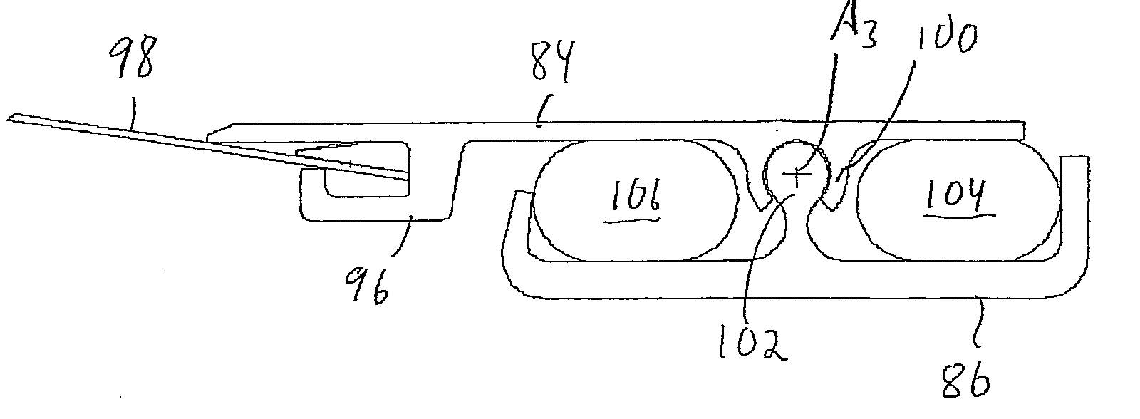
[0030]In view of the foregoing disadvantages inherent in the known types of tube loaded holders now present in prior art, the present invention provides a new holder having the advantages of reduced component counts, assembly and installation time while providing means for quick in-situ disassembly for maintenance and repair.

[0031]A primary object of the present invention is to provide a lightweight, easily constructed doctor blade holder. Another object is to provide a means for quick in-situ disassembly for maintenance and repair. Another object is to provide additional cross-machine flexibility by incorporating within the holder assembly a composite top plate having a substantial portion of reinforcing fibers therein oriented in the machine direction.

[0032]Another object is to provide for the use of a two-tube blade loading and unloading system familiar to paper machine operators and easily integrated with pre-existing equipment.

[0033]With reference to FIG. 5, a doctoring apparat...


PUM

PropertyMeasurementUnit
Structureaaaaaaaaaa
Distanceaaaaaaaaaa

Abstract

A doctor blade holder is disclosed that includes first and second members as well as position adjustment means. The first member includes a plurality of first member mounting structures that are integrally formed with the first member and are mutually spaced apart from one another along an elongated direction that is parallel with an elongated edge of a doctor blade. The second member is coupled to the first member, at least in part, by a plurality of second member mounting structures that are mutually spaced apart from one another along the elongated direction that is parallel with the elongated edge of the doctor blade. The position adjustment means is for adjusting the relative positions of the first member and the second member while the first member is coupled to the second member, at least in part, by the plurality of first member mounting structures and the plurality of second member mounting structures.

Description

PRIORITY[0001]This application claims priority to U.S. Provisional Patent Application Ser. No. 60 / 992,904 filed Dec. 6, 2007.BACKGROUND OF THE INVENTION[0002]1. Field of the Invention[0003]This invention relates to doctor blade holders, and is concerned in particular with an improved design that simplifies holder manufacturing, assembly, installation and maintenance.[0004]2. Description of the Prior Art[0005]Many roll cleaning and sheet shedding applications on papermaking machines and other web handling applications involve blade support devices commonly referred to as doctor blade holders for supporting blades such as doctor blades, creping blades and scraping blades etc.[0006]Certain prior art doctor blade holders include a top plate (to which a doctor blade is joined), a bottom plate, and a mounting and adjustment assembly between the top and bottom plates. The bottom plate is mounted on a doctorback, which is a heavy-duty beam that spans the paper machine width. The rear portio...

Claims


Application Information

Patent Timeline
IPC IPC(8): G03G21/00
CPCD21G3/005
Inventor GAUVIN, ROYALLEEMAN, DAVID
Owner KADANT INC
Why Eureka
Try Eureka