Glass substrate with protective glass, process for producing display device using glass substrate with protective glass, and silicone for release paper

a technology of glass substrate and release paper, which is applied in the direction of non-linear optics, instruments, transportation and packaging, etc., can solve the problems of affecting the production of display devices, optical defects, and the strength decrease of glass substrate caused by such a step, and achieves good adhesion properties, easy laminate of both substrates, and inclusion of bubbles

Inactive Publication Date: 2009-06-11
ASAHI GLASS CO LTD
View PDF2 Cites 37 Cited by
  • Summary
  • Abstract
  • Description
  • Claims
  • Application Information

AI Technical Summary

Benefits of technology

[0042]The glass substrate with protective glass of the present invention comprises a glass substrate and a protective glass substrate laminated on each other by a resin layer having removability, whereby by pressure bonding them by means of rolls or a press, it is possible to easily laminate the both substrates. Especially, when the glass substrate and the protective glass substrate were laminated by using a vacuum lamination method or a vacuum pressing method, inclusion of bubbles is suppressed, and adhesion properties are good. Further, even when a foreign matter such as dust is included at the interface of the laminated layers, convex defects of the glass substrates are unlikely to occur by deformation of the resin layer having flexibility.
[0043]Further, when lamination of the glass substrate and the protective glass substrate is carried out by a vacuum lamination method or a vacuum pressing method, even if very small bubbles remain, the bubbles will not grow by heating, whereby convex defects are less likely to occur in the glass substrate.
[0044]Furthermore, when a silicone resin layer having releasability and non-adhesive property, or a silicone resin layer having releasability and slight adhesive property, is used as the resin layer having removability, bubbles are hardly included particularly at the time of lamination, and even when bubbles are included, the bubbles are easily removed by carrying out press bonding by means of rolls or a press, and the heat resistance is also good.
[0045]The glass substrate with protective glass of the present invention comprises a glass substrate and a protective glass substrate laminated via a resin layer having removability, and the back surface of the glass substrate (an opposite surface from a surface on which an array or a color filter is formed) is not directly contacted to a carrier jig or a hotplate, in a step of forming a display device, whereby there is no concern that scratches are formed on the back surface of the glass substrate in the step. Further, the back surface of the glass substrate is contacted with a flexible resin layer having removability, which is fixed on the surface of the protective glass substrate, whereby it is possible to easily separate the laminate into the glass substrate and the protective glass substrate, and during the separation into the glass substrate and the protective glass substrate, no scratches are formed on the back surface of the glass substrate, and the glass substrate is unlikely to be broken.
[0046]Therefore, it is possible to significantly suppress the decrease in strength of the glass substrate after the protective glass substrate is removed and to suppress the etch pit formation when a chemical etching treatment is carried out afterwards.
[0047]In the process for producing a display device of the present invention, when a step of laminating the glass substrate on a surface of the protective glass substrate where the resin layer having removability is formed, by using vacuum pressing or vacuum lamination, it is possible to suppress inclusion of bubbles into the resin layer. As a result, there is an advantage that in a step of forming transparent electrodes of e.g. ITO under a vacuum atmosphere, it is possible to suppress formation of defects originated from air bubbles included in the resin layer.

Problems solved by technology

In the field of a medium or small sized liquid crystal display (LCD), an organic EL display device (OLED), particularly, a portable display device such as a mobile, a digital camera or a cellular phone, weight saving and reduction in thickness of a display device have been important objects, and since the reduction in thickness of the glass substrate has been progressed, the strength decrease of the glass substrate originated from such a step has especially been a serious problem.
Further, in order to make a glass substrate thinner, a step of carrying out a chemical etching treatment on a glass substrate to make the substrate thickness thin after the array / color filter bonding step, has been widely applied, but in a case where if microscopic scars formed in the above step are present on the glass substrate, pits (etch pits) having a diameter of from tens to hundreds μm will be formed on the glass substrate surface after the chemical etching treatment, which would lead to optical defects.
These methods have latent problems which may adversely affect a display device to be produced.
That is, by the method of fixing the glass substrates by means of electrostatic adsorptivity or vacuum adsorptivity, the method of fixing both ends of the glass substrates by means of glass frit, or the method of fusing the two glass substrates by irradiating the vicinity of edge surfaces of peripheral portions with laser beams, it is difficult to avoid inclusion of bubbles or convex defects due to foreign matters such as dust in the process of laminating and closely bonding the glass substrates without any interlayer, and accordingly it is difficult to obtain a glass substrate laminate having a smooth surface.
However, it is difficult to separate the glass substrate and the protective glass substrate, and the glass substrate may be broken at the time of separation.
Further, remaining of the adhesive on the glass substrate after the separation is also problematic.
Therefore, heat resistance is required for the adhesive or adhesive sheet, to be used for the display device, but a method which satisfies both heat resistance and removability has not been proposed yet.

Method used


Image

  • Glass substrate with protective glass, process for producing display device using glass substrate with protective glass, and silicone for release paper
  • Glass substrate with protective glass, process for producing display device using glass substrate with protective glass, and silicone for release paper
  • Glass substrate with protective glass, process for producing display device using glass substrate with protective glass, and silicone for release paper

Examples


example 1

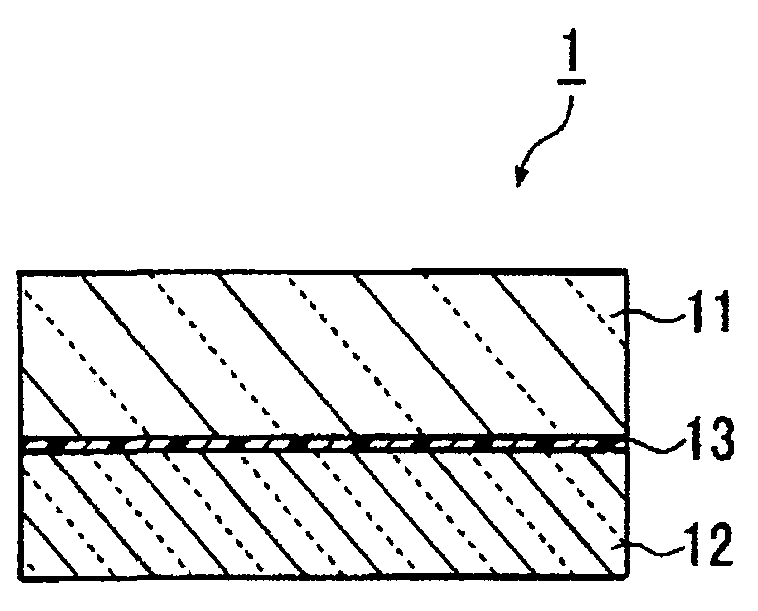
[0130]The protective glass substrate (AN100, manufactured by Asahi Glass Company, Limited) having 400 mm×300 mm×0.3 mm thick and having a linear expansion coefficient of 38×10−7 / ° C., was cleaned by e.g. purified water washing and UV washing, and then, a mixed product (application amount 30 g / m2) of 100 parts by mass of a non-solvent addition reaction type silicone for release paper (KNS-320A, viscosity: 400 cs, manufactured by Shin-Etsu Silicone) and 2 parts by mass of a platinum type catalyst (CAT-PL-56, manufactured by Shin-Etsu Silicone), was applied on the above protective glass substrate by a screen printing machine, and was heat-cured at 180° C. for 30 mins in the atmospheric air to obtain a silicone resin layer of 20 μm thick.

[0131]A surface of a glass substrate (AN100, manufactured by Asahi Glass Company, Limited) having 400 mm×300 mm×0.4 mm thick and having a linear expansion coefficient of 38×10−7 / ° C., which is to be contacted with the silicone resin layer, was cleaned b...

example 2

[0144]The glass substrate with protective glass (a glass substrate 2 with protective glass) of the present invention was obtained by carrying out the same procedures as in Example 1 except that the substrate thickness of the protective glass substrate was 0.4 mm.

[0145]In the glass substrate 2 with protective glass, the glass substrate was bonded to the silicone resin layer without forming bubbles, and it had no convex defects and had suitable smoothness.

[0146]When the simple peel test was carried out on the glass substrate 2 with protective glass, it was easy to peel the back surface protective glass substrate. Further, with respect to the glass substrate 2 with protective glass after being heat-treated at 300° C. for 1 hour in an atmosphere, the simple peel test was carried out, and it was easy to peel the back surface protective glass substrate, and the heat resistance was also suitable.

[0147]Further, in the same manner as in Example 1, with respect to the glass substrate 2 with p...

example 3

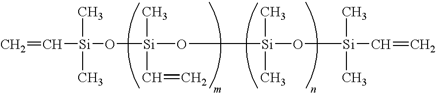
[0149]The protective glass substrate (AN100, manufactured by Asahi Glass Company, Limited) having 400 mm×300 mm×0.2 mm thick and having a linear expansion coefficient of 38×10−7 / ° C. was cleaned by e.g. purified water washing and UV washing, and then, a mixed product (application amount 20 g / m2) of a linear polyorganosiloxane having vinyl groups at both terminals (tradename “8500”, manufactured by Arakawa Chemical Industries, Ltd.), methylhydrogen polysiloxane having hydrosilyl groups in its molecule (tradename “12031” manufactured by Arakawa Chemical Industries, Ltd.), and a platinum catalyst (tradename CAT12070”, manufactured by Arakawa Chemical Industries, Ltd.), was applied on the above protective glass substrate by a screen printing machine, and was heat-cured at 180° C. for 30 minutes in an atmosphere to obtain a silicone resin layer of 20 μm thick.

[0150]Here, the mixing ratio of the linear polyorganosiloxane to methylhydrogen polysiloxane was adjusted so that the molar ratio ...


PUM

PropertyMeasurementUnit
total thicknessaaaaaaaaaa
temperatureaaaaaaaaaa

Abstract

To provide a glass substrate with protective glass which suppresses formation of microscopic scratches on the back surface of the glass substrate in the production process for a display device, and which prevents a strength decrease in the process or formation of etch pits after a chemical etching treatment; a process for producing a display device by using the glass substrate with protective glass; and silicone for release paper for the glass substrate with protective glass.A glass substrate with protective glass, which comprises a glass substrate and a protective glass substrate laminated on each other, and which is characterized in that the glass substrate and the protective glass substrate are laminated by a resin layer having removability.

Description

TECHNICAL FIELD[0001]The present invention relates to a glass substrate to be used for a display device such as a liquid crystal display or an organic EL display, more specifically, a laminated body of a glass substrate and a back-protective glass substrate, to be used for producing a display device by using such a glass substrate, a process for producing a display device by using the laminate, and silicone for release paper for the glass substrate with protective glass.BACKGROUND ART[0002]A process for producing a liquid crystal display device (LCD) generally comprises a step of forming an array on a glass substrate, a step of forming a color filter on a glass substrate different from the above glass substrate, a step of bonding the glass substrate having an array formed thereon with the glass substrate having a color filter formed thereon (an array / color filter bonding step), a step of injecting liquid crystal and a step of sealing the injection inlet. In each of the steps, since ...

Claims


Application Information

Patent Timeline
Patent Type & Authority Applications(United States)
IPC IPC(8): B32B17/10B32B7/00C08L83/04B32B37/00
CPCB32B7/06B32B7/12B32B17/10036B32B17/10972Y10T428/1476C09D183/04G02F2001/133302G02F2201/50Y10T428/2495C03C27/10Y10T428/31649Y10T428/31663Y10T428/31601Y10T428/31645G02F1/133302B32B17/10798C03C27/06C03C17/30
Inventor HIGUCHI, TOSHIHIKO
Owner ASAHI GLASS CO LTD
Why Eureka
Try Eureka