Inherently sealed electrical connector

a technology of electrical connectors and sealing plates, applied in the direction of riveted connections, coupling device connections, non-rotary current collectors, etc., can solve the problems of not being able to meet homeland security needs, current carton security systems do not meet current security needs, and requiring bulky electronics and specialized shipping cartons

Active Publication Date: 2009-06-11
INTELLISENSE SYST INC
View PDF82 Cites 97 Cited by
  • Summary
  • Abstract
  • Description
  • Claims
  • Application Information

AI Technical Summary

Benefits of technology

[0012]Durable, rugged (low-profile, button-like shape) and easy to operate (snap style)
[0016]Multi-operational, reconfigurable smart connector that can self-terminate; performs automatic routing; self-diagnose, and identify connected devices; and automatically adjust to power requirement.
[0022]The present invention represents the first fully functional wearable connector, with three major unique features: wearability and compatibility with conformability to existing and future military / civilian vests / uniforms; snap-fastener button-like style, so that it can be snapped and unsnapped “blindly” with one hand; mechanical stability and resilience not only in standard environments of temperature and humidity, but also to aggressive chemicals, water and laundering.

Problems solved by technology

Electronic devices are being miniaturized for personal use, but no comprehensive connector technology exists to integrate them into clothing in order to integrate electronics into clothing in a body-conformable and comfortable fashion.
Current carton security systems do not meet homeland security needs and require bulky electronics and specialized shipping cartons with hard cases and traditional switch-activated intrusion alarm systems.

Method used


Image

  • Inherently sealed electrical connector
  • Inherently sealed electrical connector
  • Inherently sealed electrical connector

Examples


second embodiment

[0071]In a second embodiment, the O-ring is replaced with a conductive elastomer-based sealing mechanism, which seals not only when mated but also when unmated.

[0072]The invention also comprises the integration of the wearable snap connector with narrow fabric electrical cable conduits and their embedded conductors (see FIG. 6). We enhanced self-sealing capability by connector redesign.

[0073]Reflow soldering connects the individual wires from the narrow fabric cable to the interconnect contact pads on the PCBs 15 in the snap connector as shown in FIG. 7.

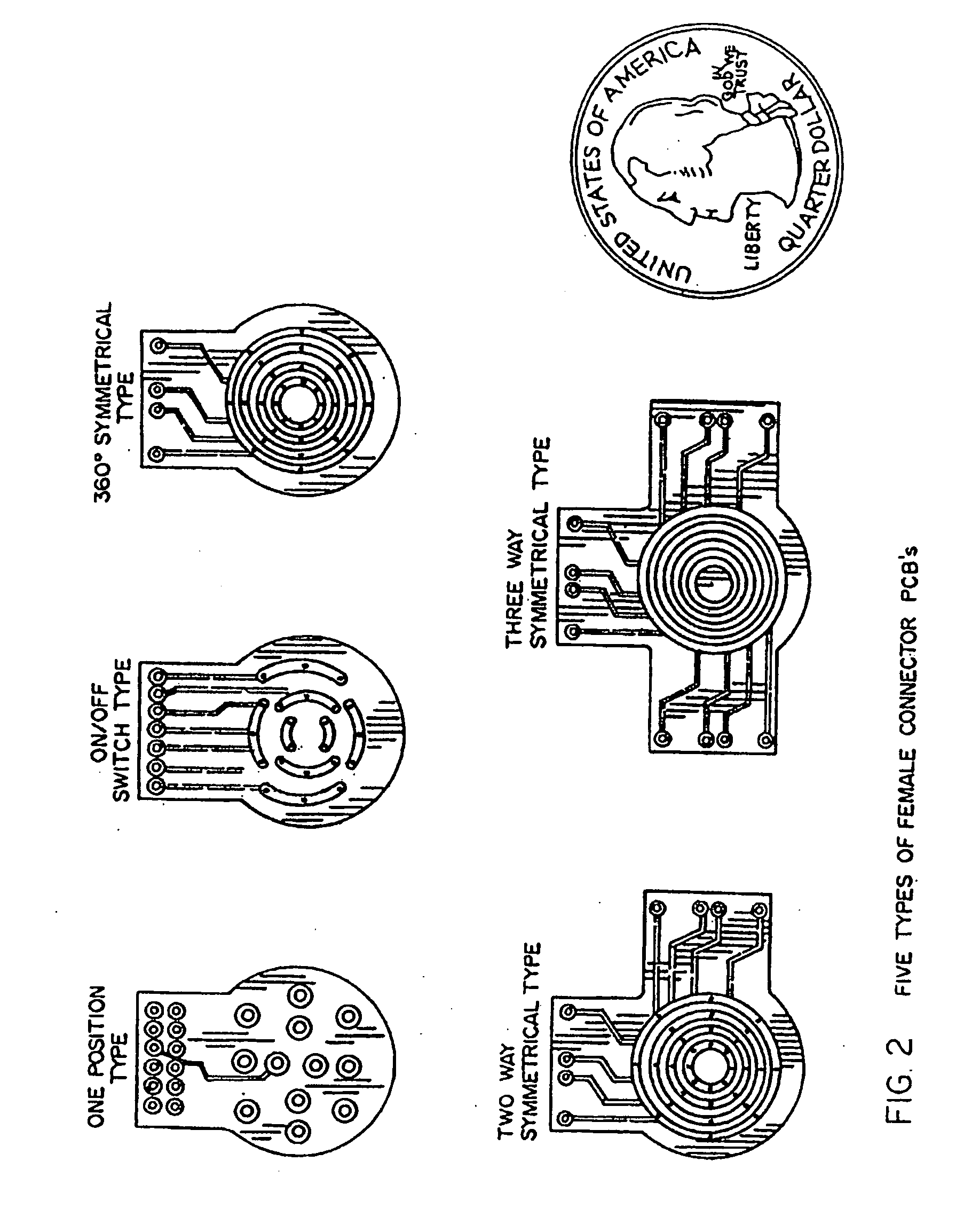
[0074]Although one can manufacture woven e-textile cables, the connector is designed to fully integrate with existing narrow fabric cables in various configurations, accommodating the existing form factor and electrical specifications, as shown in FIG. 8. The female connector configuration can be varied to increase the degrees of freedom in the interconnectivity of devices within the network.

[0075]One can easily apply the highway ana...

fifth embodiment

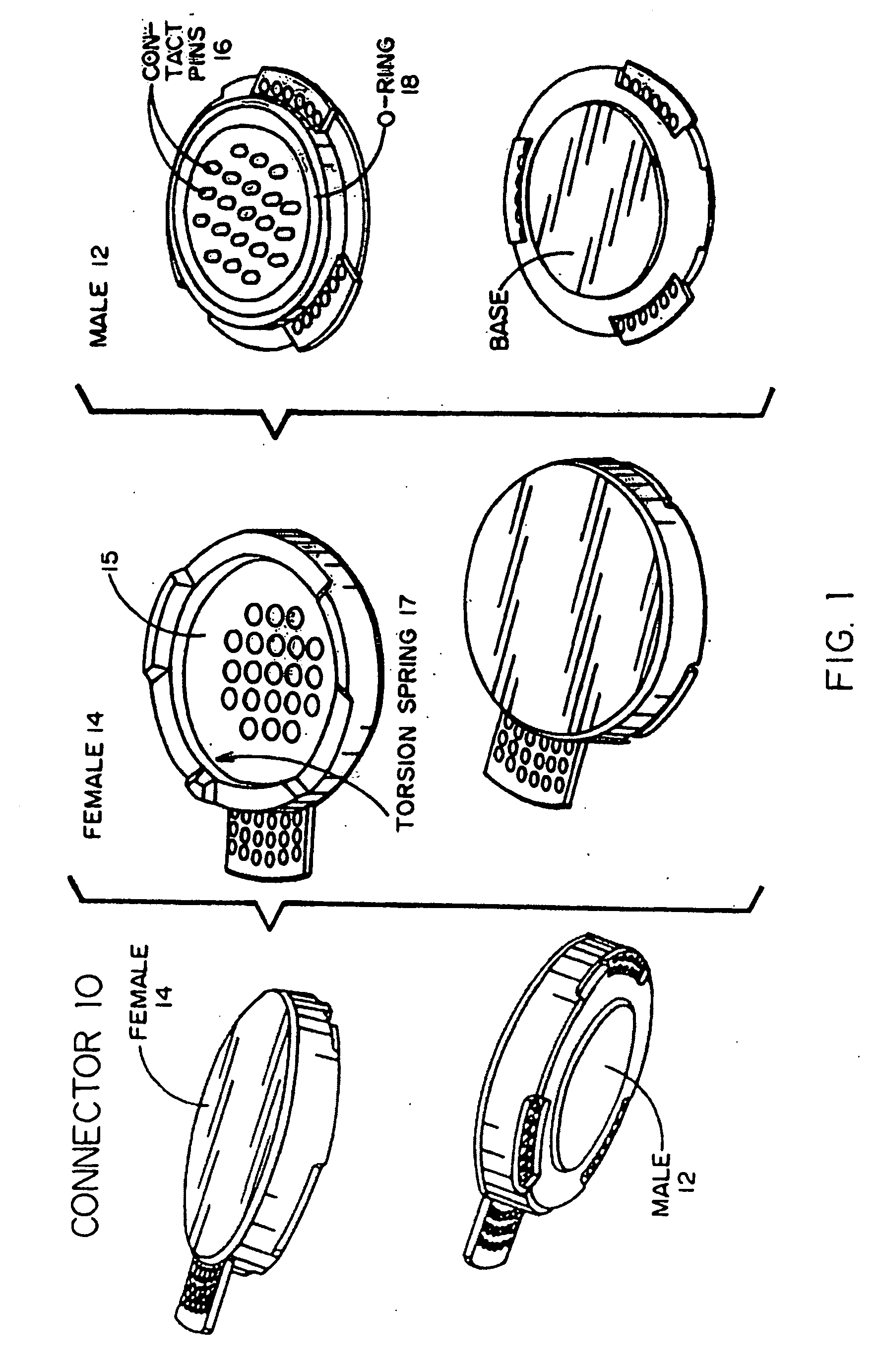
[0110]FIGS. 23 to 25 illustrate the fifth version of the invention, which is the smallest wearable connector currently developed. As seen in FIG. 25, this embodiment (even with a center coax plug) is a little greater in diameter than the diameter of a U.S. dime. It is configured to have the same appearance, tactile feel and function of a conventional fabric snap fastener as shown in FIG. 23. FIG. 24 illustrates the individual components of the male 30 and female 40 connector of this fifth embodiment, namely caps 32, socket 34, contact pad 36, torsion spring 38, spring contacts 42, contact pad 44, torsion spring 45, eyelet 46 and base 48.

[0111]FIG. 26 shows a Smart Connectorized Pouch. The garment pouch is suitably sized for receiving an electronic device and having a wearable connector at the end of a short length of fabric ribbon within the pouch. The connector attaches to the device held in the pouch thereby providing both electrical interface and mechanical support. In some cases...


PUM


Abstract

An entirely wearable electrical connector for power / data connectivity. The principal element of a modular network is the wearable electrical connector, which is integrated into a personal area network with USB compatibility. An embodiment comprises a non-conductive elastomeric environmental seal.

Description

CROSS-REFERENCE TO RELATED APPLICATIONS[0001]This application is a divisional of and claims priority from U.S. application Ser. No. 11 / 190,697 filed Jul. 27, 2005, which is hereby incorporated herein by reference in the entirety.STATEMENT OF RIGHTS TO INVENTIONS MADE UNDER FEDERALLY SPONSORED RESEARCH[0002]The invention described herein was made with Government support under contract W911 QY-04-C-0038 awarded by the U.S.A. Soldier Systems Center in which the Government has certain rights in the invention.FIELD OF THE INVENTION[0003]The present invention relates to a connector configured as a fastening element. Some embodiments are in the form of a wearable electrical connector and associated connector system.BACKGROUND[0004]Electronic devices are being miniaturized for personal use, but no comprehensive connector technology exists to integrate them into clothing in order to integrate electronics into clothing in a body-conformable and comfortable fashion. The present invention compr...

Claims


Application Information

Patent Timeline
Patent Type & Authority Applications(United States)
IPC IPC(8): H01R33/965
CPCA41D1/002H01R4/04H01R4/06H01R12/592H01R39/64H01R13/5219H01R13/625H01R13/6277H01R13/24
Inventor LEE, KANGFORRESTER, THOMASJANNSON, TOMASZKOSTRZEWSKI, ANDREWLEVIN, EUGENESAVANT, GAJENDRA
Owner INTELLISENSE SYST INC
Why Eureka
Try Eureka