Method, device and structure for joining two members together

a technology of two members and a structure, applied in the field of methods, devices and structures for joining two members together, can solve the problem of insufficient strength and achieve the effect of sufficient peel strength

Inactive Publication Date: 2009-06-18
SHIROKI KOGYO CO LTD
View PDF17 Cites 8 Cited by
  • Summary
  • Abstract
  • Description
  • Claims
  • Application Information

AI Technical Summary

Benefits of technology

[0021]According to the present invention, the two members (the holed member and the unholed member) can be joined together with a sufficient peel strength because the flat portion of the holed member around the through-hole is deformed into the shape of a truncated conical projection while the unholed member is deformed along the truncated conical projection to partly project from the through-hole in the case of deforming the unholed member (member with no through-hole) against a portion around a through-hole formed in the holed member (member with a through-hole).

Problems solved by technology

However, in the joining structure disclosed in JUPP H07-132422, since the half shear portion is simply in intimate contact with the inner surface of the through-hole and also since the peel strength is determined by the frictional resistance between the half shear portion and the inner surface of the through-hole, a sufficient strength cannot be obtained especially when the thickness of the member in which the through-hole is formed is small.

Method used


Image

  • Method, device and structure for joining two members together
  • Method, device and structure for joining two members together
  • Method, device and structure for joining two members together

Examples


Embodiment Construction

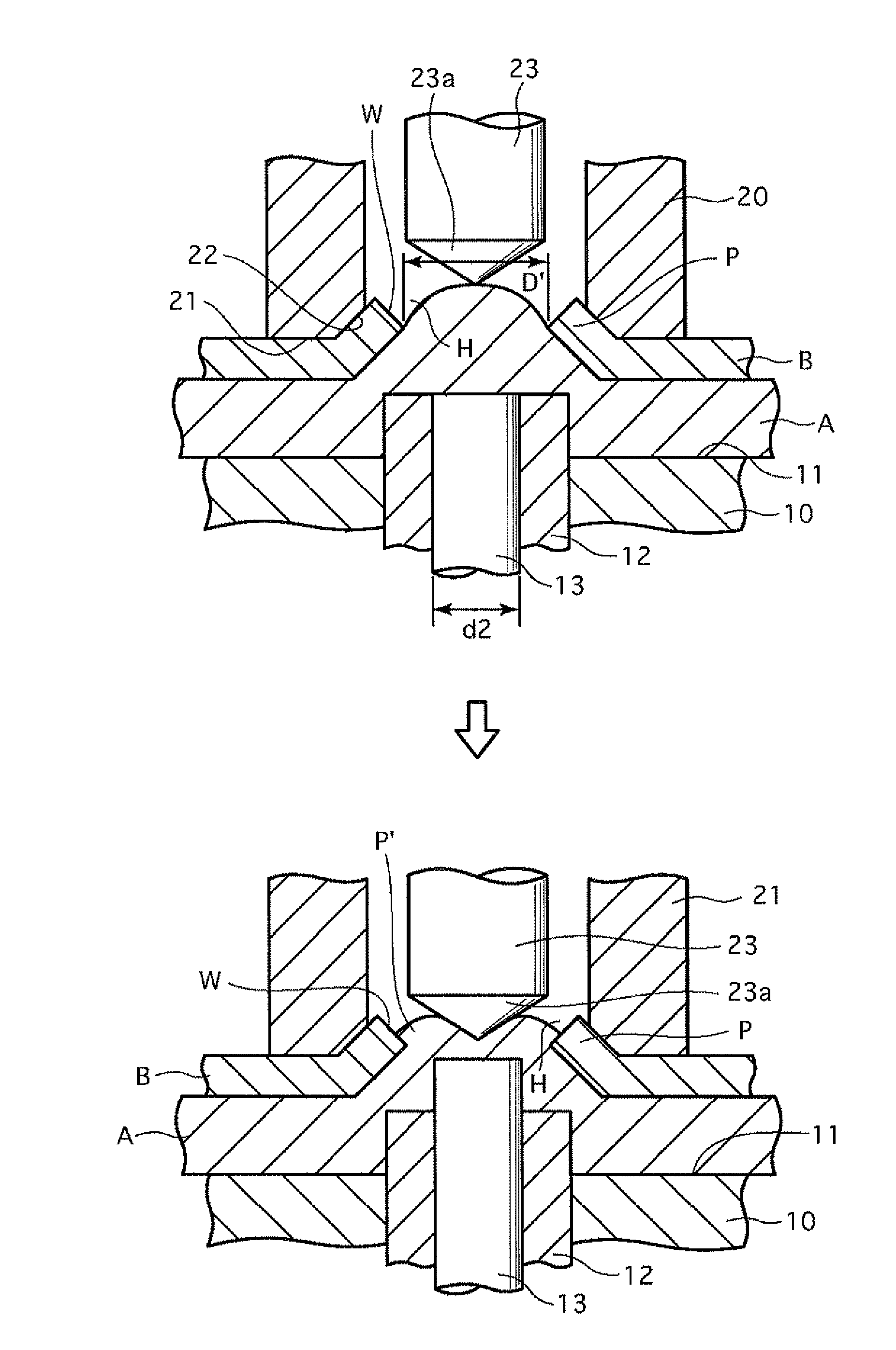
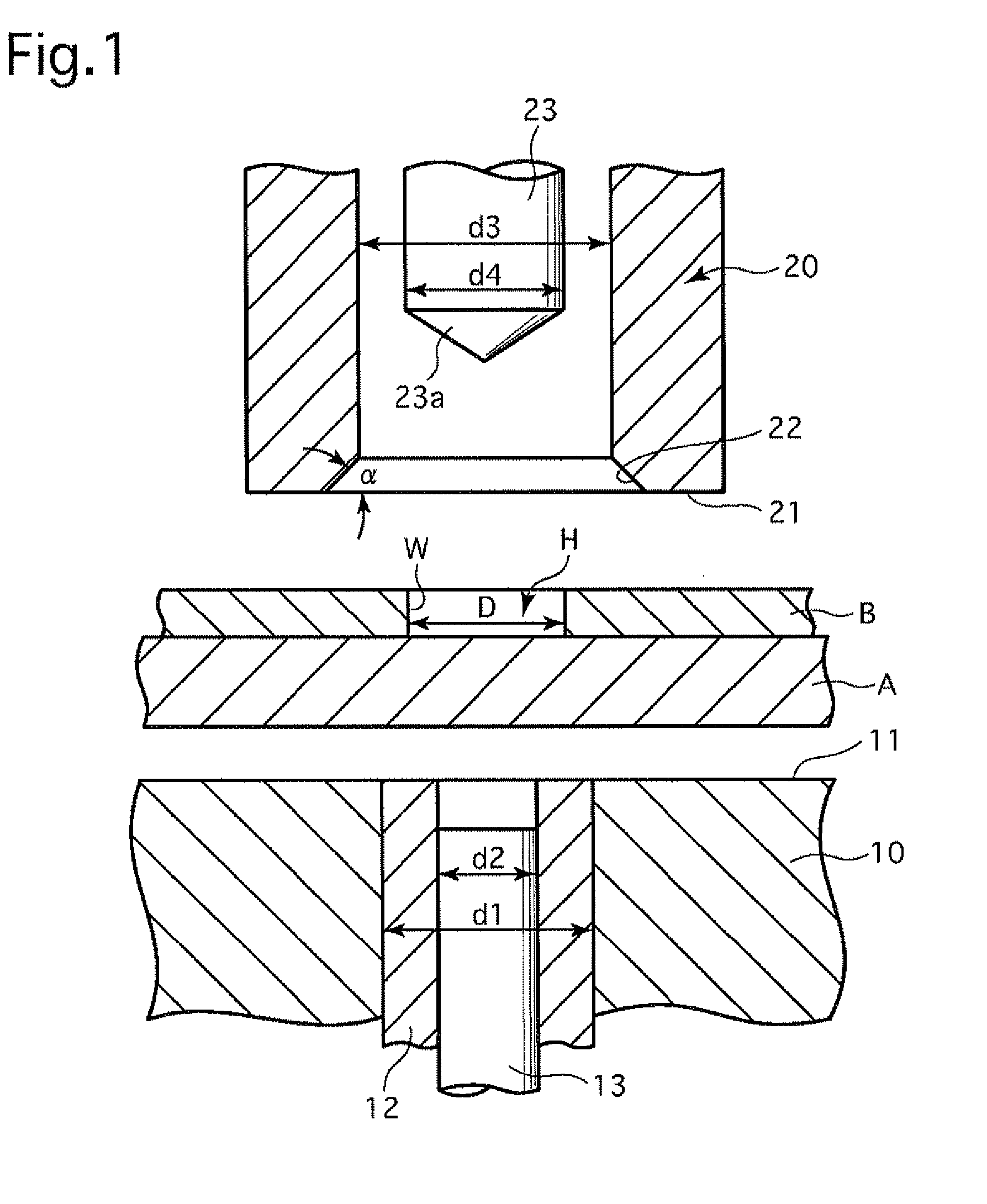
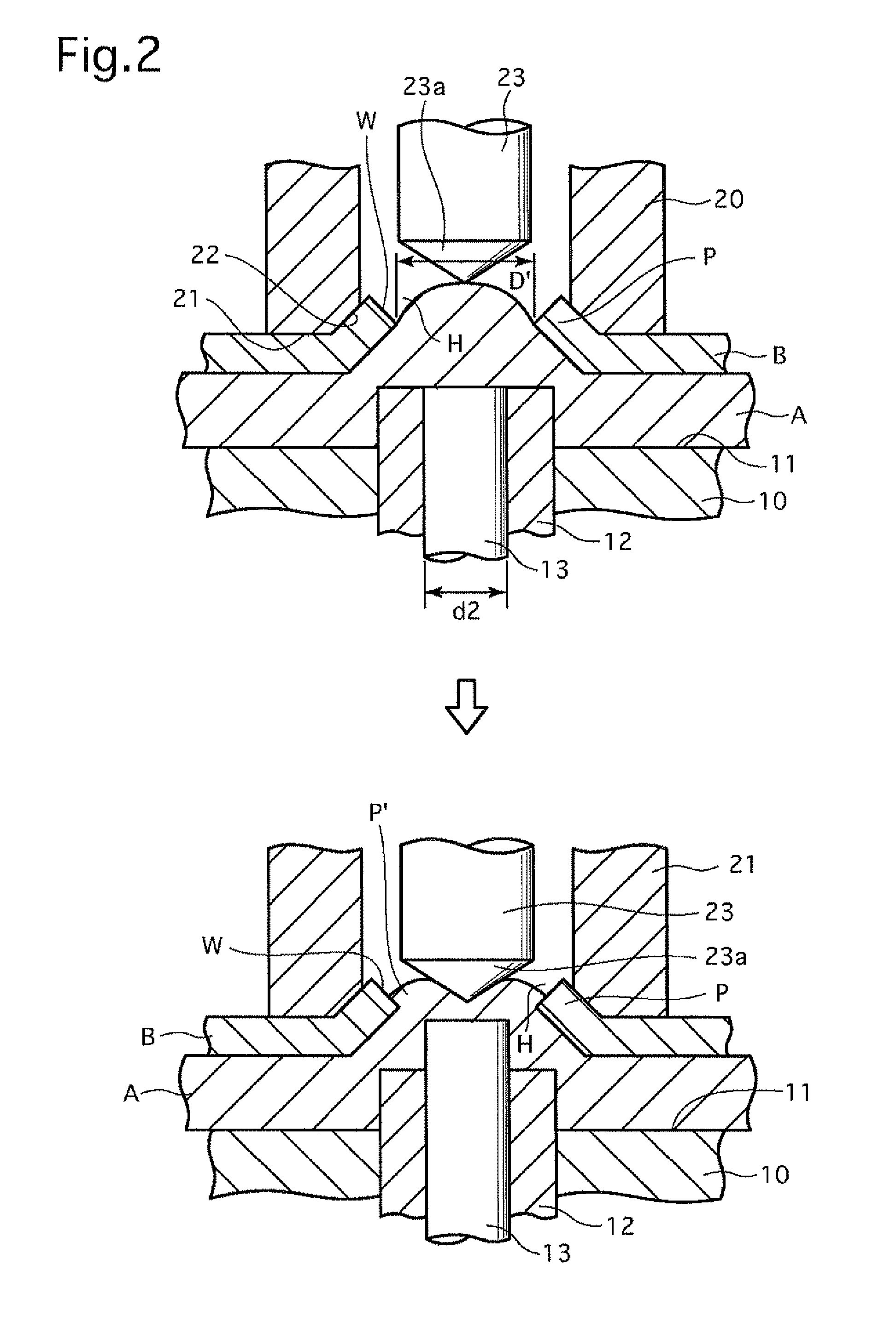
[0026]FIG. 1 shows an embodiment of a joining device that operates to implement a method of joining two members together. The joining device is used to join a non-through-holed member (unholed member / plate / board) A that does not include a through-hole and a through-holed member (holed member / plate / board) B that includes a through-hole H having an inner diameter D. The joining device is provided with a swaging base 10 and a die 20 which are movable relative to each other in directions toward and away from each other. All the elements of the joining device are rotationally symmetrical with respect to an axis (central axis of the through-hole H).

[0027]The swaging base 10 is provided with a flat mounting surface 11 on which the non-through-holed member A is mounted. The swaging base 10 is further provided with a first base swaging punch 12 and a second base swaging punch 13 each of which advances and retreats (moves upward and downward with respect to FIG. 1) from the flat mounting surf...


PUM

PropertyMeasurementUnit
shapeaaaaaaaaaa
diameteraaaaaaaaaa
peel strengthaaaaaaaaaa

Abstract

A method for joining a holed member, including a through-hole, and an unholed member together, the method includes deforming the unholed member against the through-hole of the holed member so that a flat portion of the holed member around the through-hole is deformed into the shape of a truncated conical projection and so that the unholed member is deformed along the truncated conical projection to partly project from the through-hole, and deforming a portion of the unholed member which projects from the through-hole to come into intimate contact with a wall surface of the through-hole of the holed member.

Description

BACKGROUND OF THE INVENTION[0001]1. Field of the Invention[0002]The present invention relates to a method, a device and a structure for joining two members together.[0003]2. Description of the Prior Art[0004]A method and an apparatus for joining two members together with no welding is known in the art and disclosed in Japanese unexamined patent publication H07-132422. This method and this apparatus are based on attention being directed to forming a through-hole in one of the two members in advance and forming a half shear portion on the other member which is brought into intimate contact with the inner surface of the through-hole, wherein the half shear portion is formed by squeezing a part of the other member into the through-hole with a first punch (punch for forming the half shear portion) and wherein the half shear portion is brought into intimate contact with the inner surface of the through-hole by swaging the half shear portion in lateral directions with a second punch (punch...

Claims


Application Information

Patent Timeline
Patent Type & Authority Applications(United States)
IPC IPC(8): B23P11/00B21D39/03
CPCB21D39/032B21K25/00Y10T29/53996Y10T29/49938F16B5/045
Inventor NAGAI, KOUSUKEANDO, OSAMUJIUCHI, KOUHEI
Owner SHIROKI KOGYO CO LTD
Why Eureka
Try Eureka