Bracing and spacing apparatus for hip trusses

a technology for bracing and spacing, which is applied in the direction of load-supporting braces, building roofs, building components, etc., can solve the problems of not being able to brace adjacent hip trusses, requiring a bit more complex trusses, and being more difficult to construct hip roofs

Inactive Publication Date: 2009-06-18
STALEY SCOTT
View PDF9 Cites 25 Cited by
  • Summary
  • Abstract
  • Description
  • Claims
  • Application Information

AI Technical Summary

Benefits of technology

[0008]The subject invention rather broadly provides an apparatus for accurately spacing hip roof trusses during the erection process and for permanently bracing adjoining hip roof trusses. More particularly, the instant apparatus is designed to interconnect at predetermined distances the horizontal top chord members of adjacent hip trusses for proper spacing and support purposes. A preferred and basic embodiment of the subject apparatus is comprised of a longitudinal member terminating at each end in truss attachment means adapted for fastening to the horizontal top chord of adjacent hip trusses of different heights. An important characteristic of each embodiment of the subject invention is that a first attachment means is angled above the plane of the longitudinal member while the second attachment means is angled below the same plane, each depending from the longitudinal member at equal but opposite angles. Thusly oriented, each attachment means occupies a plane parallel to the other with the plane of the longitudinal member intersecting both. The slope of the longitudinal member between the parallel planes is predetermined to substantially correspond to the desired pitch of the roof. The span component of this slope will always be equal to the desired distance between hip trusses so that when the apparatus is employed proper hip truss spacing is ensured. Similarly, the rise component of the slope of the apparatus (or the distance between planes of the attachment means) will always be equal to the difference in height between top chords of adjacent hip trusses. The unique construction of the subject apparatus therefore allows it to serve as a template for proper orientation of neighboring hip trusses relative to one another with each attachment means coming into abutting (coplanar) engagement with the top surface of each horizontal top chord member for permanent fastening.

Problems solved by technology

Hip roofs are more difficult to construct, requiring somewhat more complex systems of trusses as described herein.
Accordingly, because of the unique shape of hip trusses and their orientation relative to one another it is not practical to brace adjoining hip trusses at or in proximity to their center point which is the most logical point of placement of at least some bracing members.
Another problem associated with the construction of hip roofs is that once the temporary bracing is in place, it is often necessary to adjust the spacing of the trusses which requires complete or partial detachment of the bracing strips.
Such a practice is dangerous because the removal of bracing can cause trusses to topple if a key connection is removed at the wrong time.
Therefore, it becomes critical to achieve exact spacing of trusses as temporary bracing is applied, an objective which those skilled in the art recognize is difficult to accomplish because truss top chords are very susceptible to lateral buckling before they are braced or sheathed.
In addition to the safety issue, removal of temporary bracing is time consuming and often damages the bracing boards so that they cannot be used again.
Conventional employment of temporary bracing therefore results in wasted material.

Method used


Image

  • Bracing and spacing apparatus for hip trusses
  • Bracing and spacing apparatus for hip trusses
  • Bracing and spacing apparatus for hip trusses

Examples


Embodiment Construction

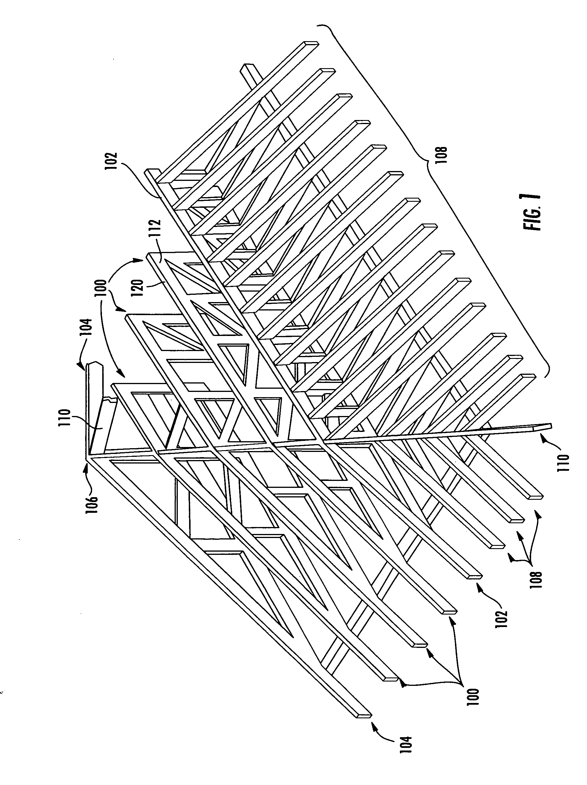
[0025]In order that the construction and benefits of the subject invention may be fully appreciated it is first necessary to understand the environment within which it is installed, namely a framed hip roof system. Reference first being made to FIG. 1, a typical hip roof end is built up of flat top hip trusses 100 arranged in a stepped up sequence beginning with a hip girder 102 and terminating in a common truss 104 the apex 106 of which serves as the peak of the hip. The truncated girder truss 102 is there to give extra strength to the hip areas. They are usually double the thickness of the ordinary trusses (two trusses of the same thickness nailed together). A plurality of hip jack trusses 108 complete the framing system some of which are attached to hip girder 102 while others are attached to diagonal hip rafter 110 as shown. Note that the hip rafters 110 form the “hip” of the roof.

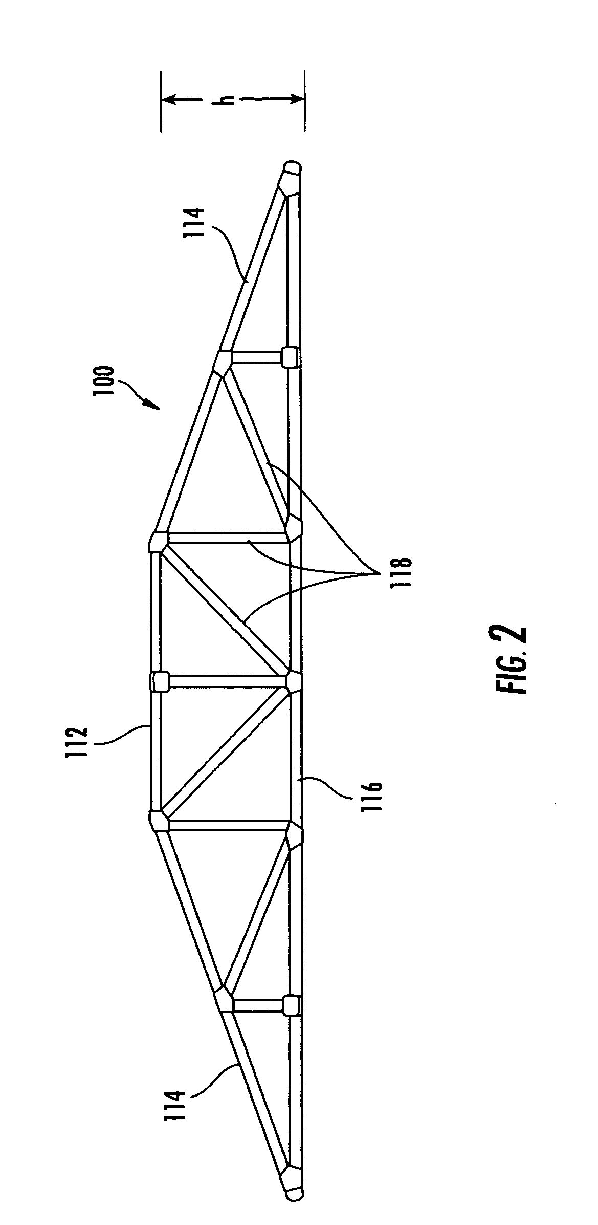
[0026]Referring next to FIG. 2, a typical hip truss 100 is comprised of a horizontal top chord memb...


PUM


Abstract

An apparatus for accurately spacing neighboring hip roof trusses during the erection process and for permanently bracing the same is comprised of a longitudinal member terminating at each end in truss attachment means adapted for fastening to the horizontal top chord of adjacent hip trusses of different heights. An important characteristic of each embodiment of the subject invention is that a first attachment means is angled above the plane of the longitudinal member while the second attachment means is angled below the same plane, each depending from the longitudinal member at equal but opposite angles. Thusly oriented, each attachment means occupies a plane parallel to the other with the plane of the longitudinal member intersecting both. The slope of the longitudinal member between the parallel planes is predetermined to substantially correspond to the desired pitch of the roof.

Description

FIELD OF THE INVENTION[0001]The subject invention relates generally to an apparatus for bracing roof trusses, and to a bracing apparatus for hip roof trusses in particular.BACKGROUND OF THE INVENTION[0002]Hip roofs (or “hipped roofs” as they are sometimes referred) have achieved considerable popularity among builders of residential homes and commercial buildings particularly in areas like Northern Australia and the Gulf Coast of the Southeastern United States where such structures are exposed to high wind loadings. Because of their unique design characteristics, hipped roofs are capable of reducing or eliminating the airfoil effect of extreme high winds that blow over the roof often causing it to peel off the structure. Such a benefit makes them ideal for hurricane prone regions. The hip roof also exhibits increased survivability in tornadic winds.[0003]In general, a hip roof is a type of roof where all sides slope downwards to the walls, usually with a fairly gentle slope. Thus it ...

Claims


Application Information

Patent Timeline
Patent Type & Authority Applications(United States)
IPC IPC(8): E04B1/38
CPCE04C2003/026E04B7/063E04G21/1891
Inventor STALEY, SCOTT
Owner STALEY SCOTT
Why Eureka
Try Eureka