Sub-Caliber Projectile

a sub-caliber, projectile technology, applied in the direction of ammunition projectiles, weapons components, ammunition, etc., to achieve the effect of improving the flight properties, improving the flight stability, and improving the flight properties of the projectil

Inactive Publication Date: 2009-06-18
WINTER UDO
View PDF20 Cites 4 Cited by
  • Summary
  • Abstract
  • Description
  • Claims
  • Application Information

AI Technical Summary

Benefits of technology

[0010]If the tail unit has a section which is setback by the wall thickness of the hollow projectile head and receives the projectile head, a continuous transition from the projectile head to the tail unit may be ensured easily, which improves the flight properties of the projectile. To further improve the flight properties, the vanes of the tail unit may form a control surface inclined in relation to an axial plane in the area of its rear end, which ensures a torque around the projectile axis because of the flow conditions against it, so that the flight stability is increased as a result of the rotation of the projectile around its axis connected thereto.
[0011]The projectile head may have a setback annular shoulder, which is not only used for the axial support of the projectile receptacle in relation to the projectile, but rather also may provide a contribution to the flight stabilization of the projectile. If the annular shoulder is shaped into an axial annular web having radial notches or slots distributed around the circumference, the effect of the projectile upon incidence on the target may additionally be lastingly influenced, because this annular web tears apart axially as a result of the notches and / or slots and is bent radially outward. A similar effect may be achieved by other implementations of the projectile head, for example, in that the projectile head has an annular bead formed by a centric or annular recess on the front face, which is provided with radial notches or slots distributed around the circumference, which in turn result in an expansion of the annular bead upon incidence of the projectile on a target. To support the mushrooming expansion of the projectile head, the centric recess in the projectile head may extend up to the cavity of the tail unit, a spreading core projecting into the cavity of the tail unit being inserted into the recess, which engages with an annular shoulder in an expansion of the recess provided adjoining the tail unit in the projectile head. Upon incidence of the projectile on the target, the annular bead is additionally expanded with the aid of the annular shoulder of the spreading core by the kinetic energy of the spreading core, by which the effect of the projectile is improved.
[0012]To improve the penetrating power of the projectile, the projectile head may have an insert made of a heavier material, whose greater kinetic energy may be used for specific intended purposes. If a softer insert is selected, the plastic deformation of the insert may be used for a special projectile effect upon incidence on a harder target. The projectile head may also be molded from a granular material, however, which disintegrates upon incidence on a target.
[0013]To increase the penetrative force of a projectile, an opening which lengthens the cavity of the tail unit may also be provided in the projectile head to receive a hard projectile core extending into the cavity of the tail unit, which, upon joining of projectile head and tail unit, is held between these design parts without additional measures. Because of its kinetic energy, the projectile core penetrates the front face of the projectile head upon incidence of the projectile on the target and penetrates into the target object.

Problems solved by technology

A complex production method results because this connection requires a melting procedure.

Method used


Image

  • Sub-Caliber Projectile
  • Sub-Caliber Projectile
  • Sub-Caliber Projectile

Examples


Embodiment Construction

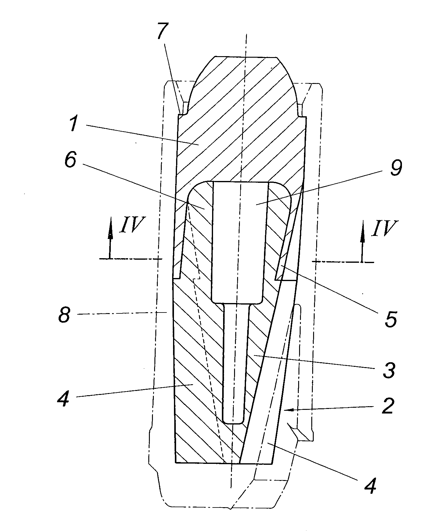
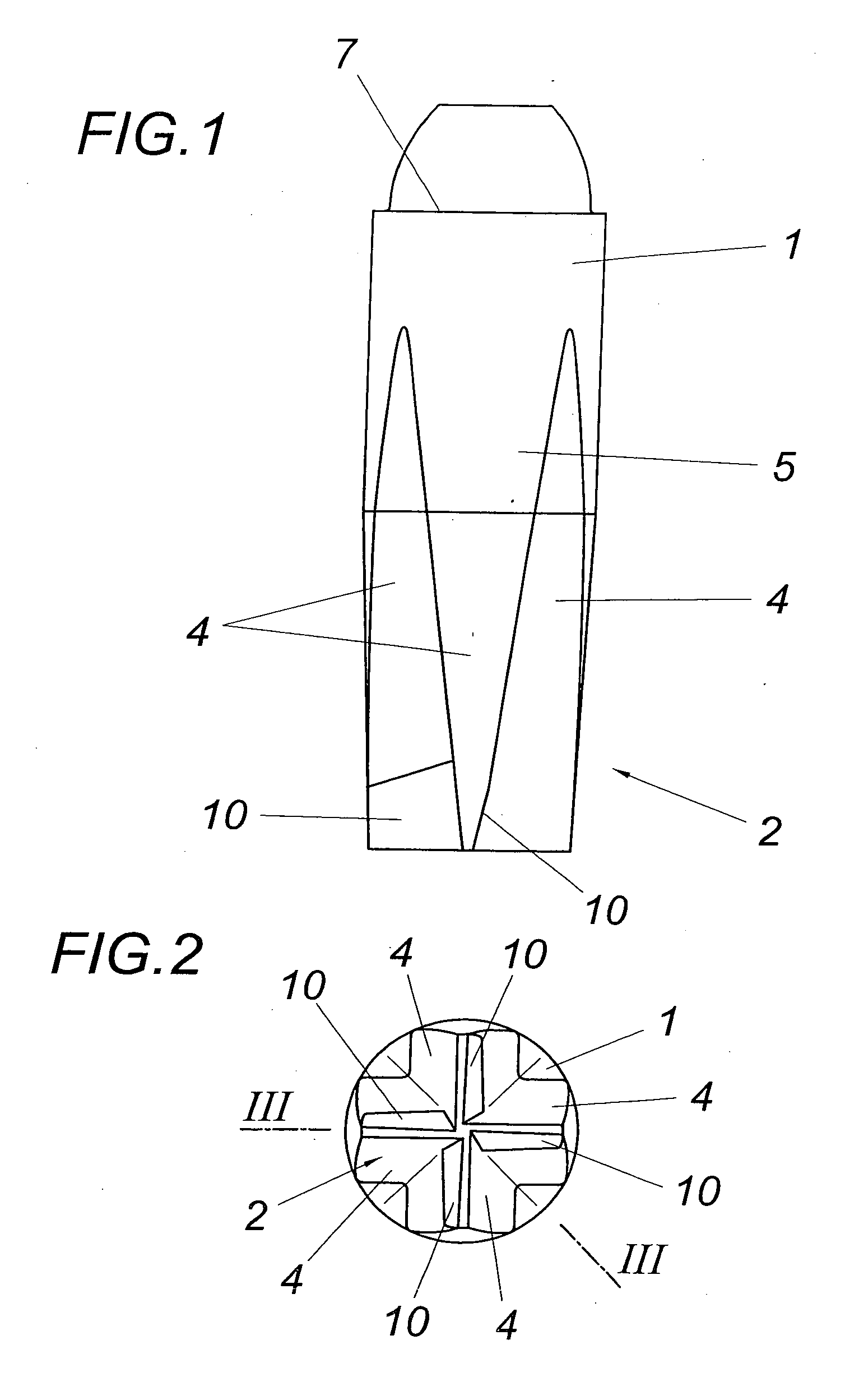
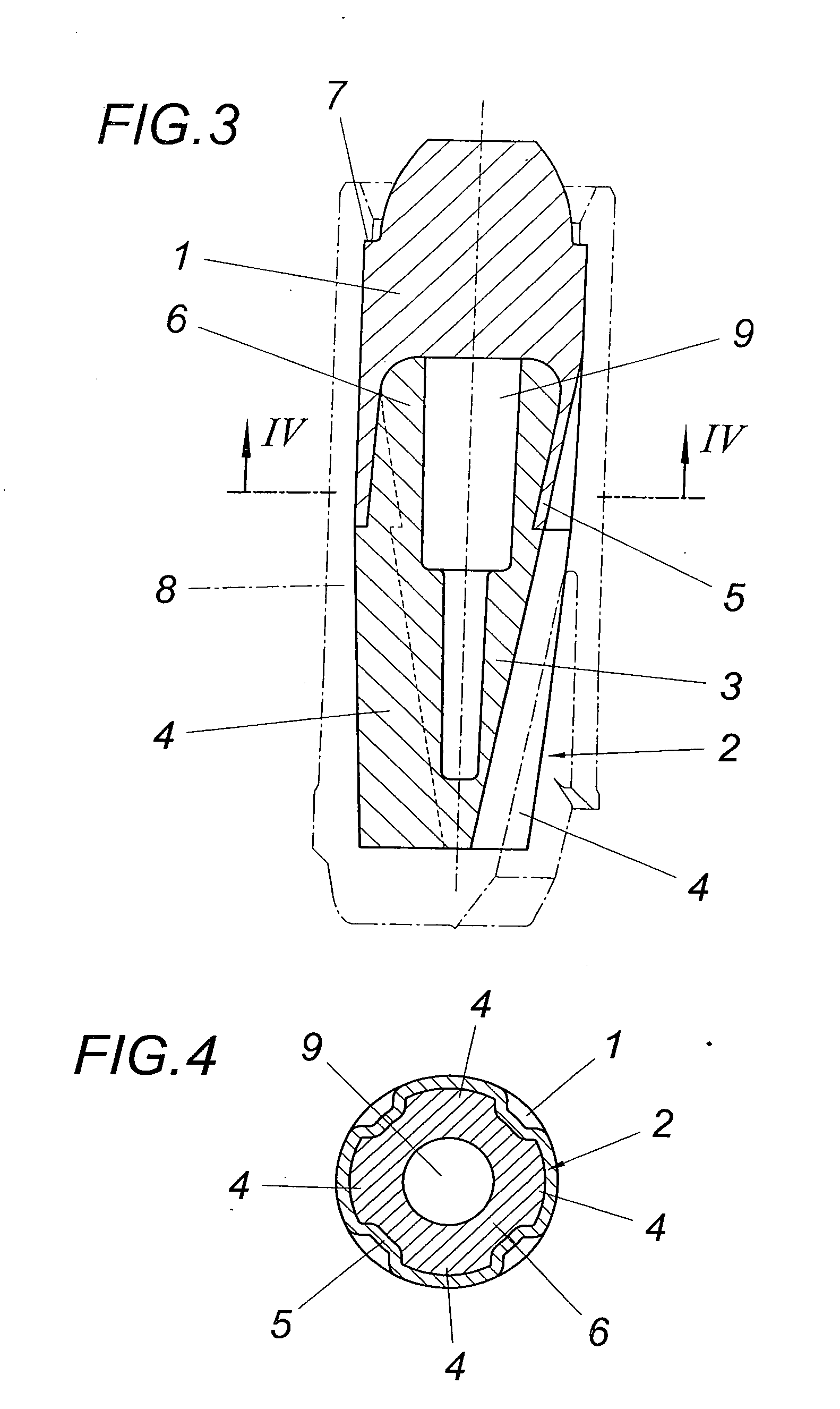
[0020]The projectile according to the exemplary embodiment from FIGS. 1 through 4 has a projectile head 1 and a tail unit 2 having guide vanes 4 projecting radially from a main body 3. The configuration is selected in such a manner that the main body 3 tapers away from the projectile head 1 toward the projectile base, while the guide vanes 4 taper off toward the projectile head 1. The projectile head 1 is implemented as hollow and has a pot shape, whose wall is identified by 5. An axial section 6 of the tail unit 2 engages in this pot shape of the projectile head 1, as may be inferred from FIGS. 3 and 4 in particular. The guide vanes 4 extend up into the area of the projectile head 1, whose wall 5 is folded into the groin area between the guide vanes 4, which is obvious above all from FIGS. 3 and 4. This folding in of the wall 5 in accordance with the course of the guide vanes 4 provides a formfitting, self-centering clamped seat between the projectile head 1 and the tail unit 2. Be...


PUM


Abstract

A sub-caliber projectile is described for insertion into a projectile receptacle (8) having a projectile head (1) and a tail unit (2) forming guide vanes (4), which engages in a cavity of the projectile head (1). To provide advantageous construction conditions, it is suggested that the guide vanes (4) of the tail unit (2) extend up into the hollow projectile head (1) and the projectile head (1) be folded clamped into the groin area between the guide vanes (4).

Description

1. FIELD OF THE INVENTION[0001]The invention relates to a sub-caliber projectile for use in a projectile receptacle having a projectile head and a tail unit forming guide vanes, which engages in a cavity of the projectile head.2. DESCRIPTION OF THE PRIOR ART[0002]Sub-caliber projectiles require a projectile receptacle for sealing the projectile in relation to the barrel of a shotgun, for example. The projectile receptacle, which may be implemented as a propellant cup, sabot, or propellant collar, is inserted together with the projectile in a cartridge casing, from which it is driven out after the firing of the propellant charge of the cartridge with the aid of the resulting propellant gases together with the projectile in the barrel. After leaving the barrel, the projectile receptacle is separated from the projectile, which flies further. For this purpose, the projectile receptacle may be provided with intended separation points distributed around the circumference, which cause an u...

Claims


Application Information

Patent Timeline
Patent Type & Authority Applications(United States)
IPC IPC(8): F42B14/06
CPCF42B10/22
Inventor WINTER, UDO
Owner WINTER UDO
Why Eureka
Try Eureka