Fuel-feeding devices

a technology of fuel-feeding devices and liquid fuel, which is applied in the direction of liquid fuel feeders, machines/engines, positive displacement liquid engines, etc., can solve the problems of wasteful operation of fuel pumps and inability to control liquid fuel flow rate, so as to reduce the volume of liquid fuel and reduce the load on the fuel pump

Inactive Publication Date: 2009-06-18
AISAN IND CO LTD
View PDF34 Cites 11 Cited by
  • Summary
  • Abstract
  • Description
  • Claims
  • Application Information

AI Technical Summary

Benefits of technology

[0007]According to the fuel-feeding device thus constructed, the liquid fuel in the reservoir cup can be fed to the engine by the fuel pump. Further, a pressure of the liquid fuel pumped out of the fuel pump can be controlled by the pressure regulator. Further, the pressurized liquid fuel pumped out of the fuel pump can be fed to the jet pump via the fuel jet path. The jet pump can be actuated with the aid of flow of the liquid fuel, so that the liquid fuel outside of the reservoir cup is introduced into the reservoir cup. The flow rate control valve may preferably change a flow rate of the pressurized liquid fuel fed to the jet pump depending upon a pumping rate of the pressurized liquid fuel pumped from the fuel pump. Therefore, when the pumping rate of the liquid fuel pumped from the fuel pump is low, the flow rate of the pressurized liquid fuel fed to the jet pump may preferably be reduced. As a result, a flow rate of the liquid fuel fed to the engine may preferably be prevented from being excessively reduced. Thus, it is not necessary to actuate the fuel pump 16 at a relatively high speed in order to fed the reduced volume of liquid fuel to the engine. In other words, when the reduced volume of liquid fuel should be fed to the engine, a load applied to the fuel pump can be effectively reduced.

Problems solved by technology

However, according to the known fuel-feeding device, it is not possible to control a flow rate of the liquid fuel pumped from the relief port of the fuel pump.
This means that when the reduced volume of liquid fuel should be fed to the engine, the fuel pump must be wastefully actuated.

Method used


Image

  • Fuel-feeding devices
  • Fuel-feeding devices
  • Fuel-feeding devices

Examples


first embodiment

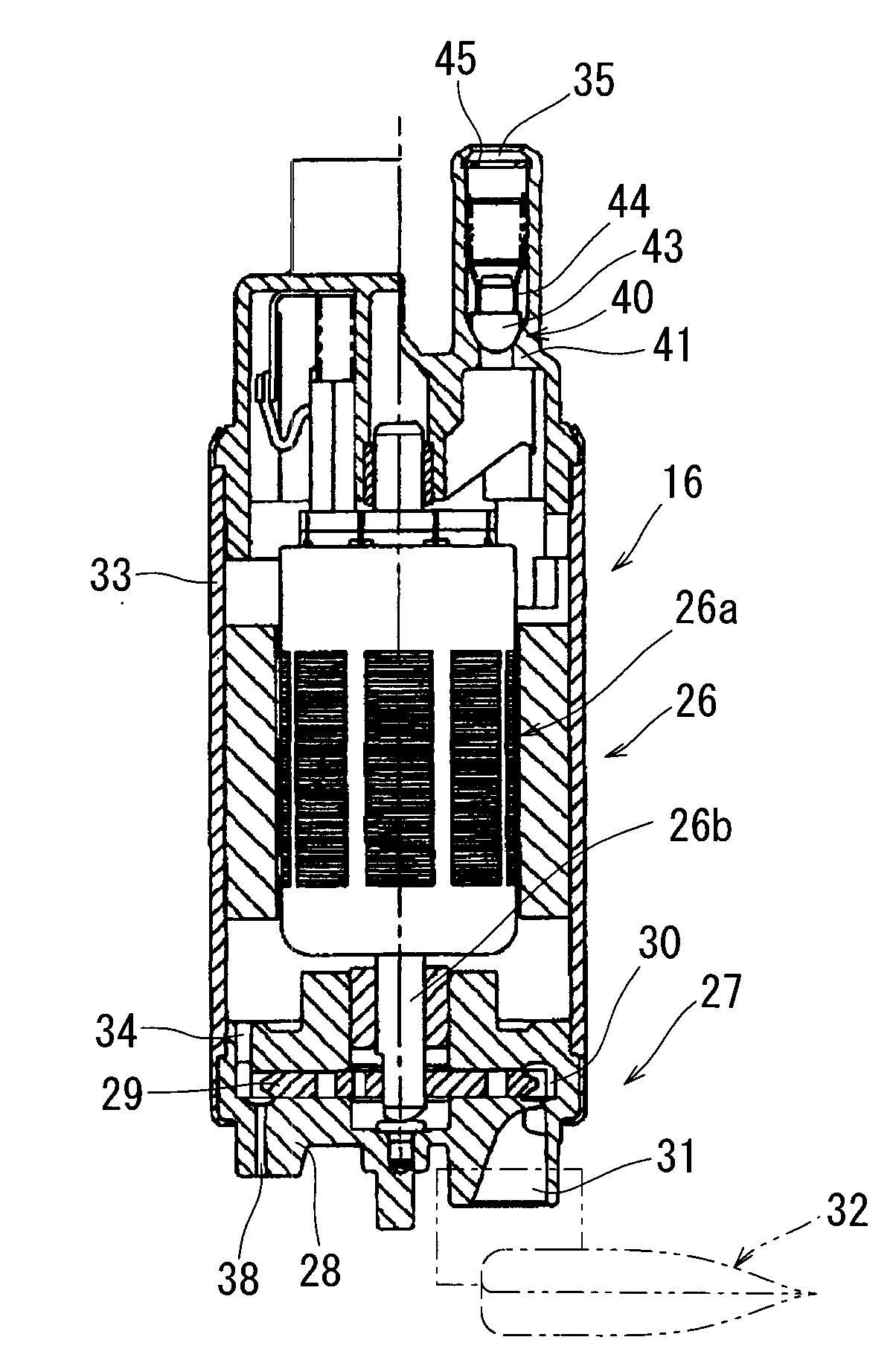
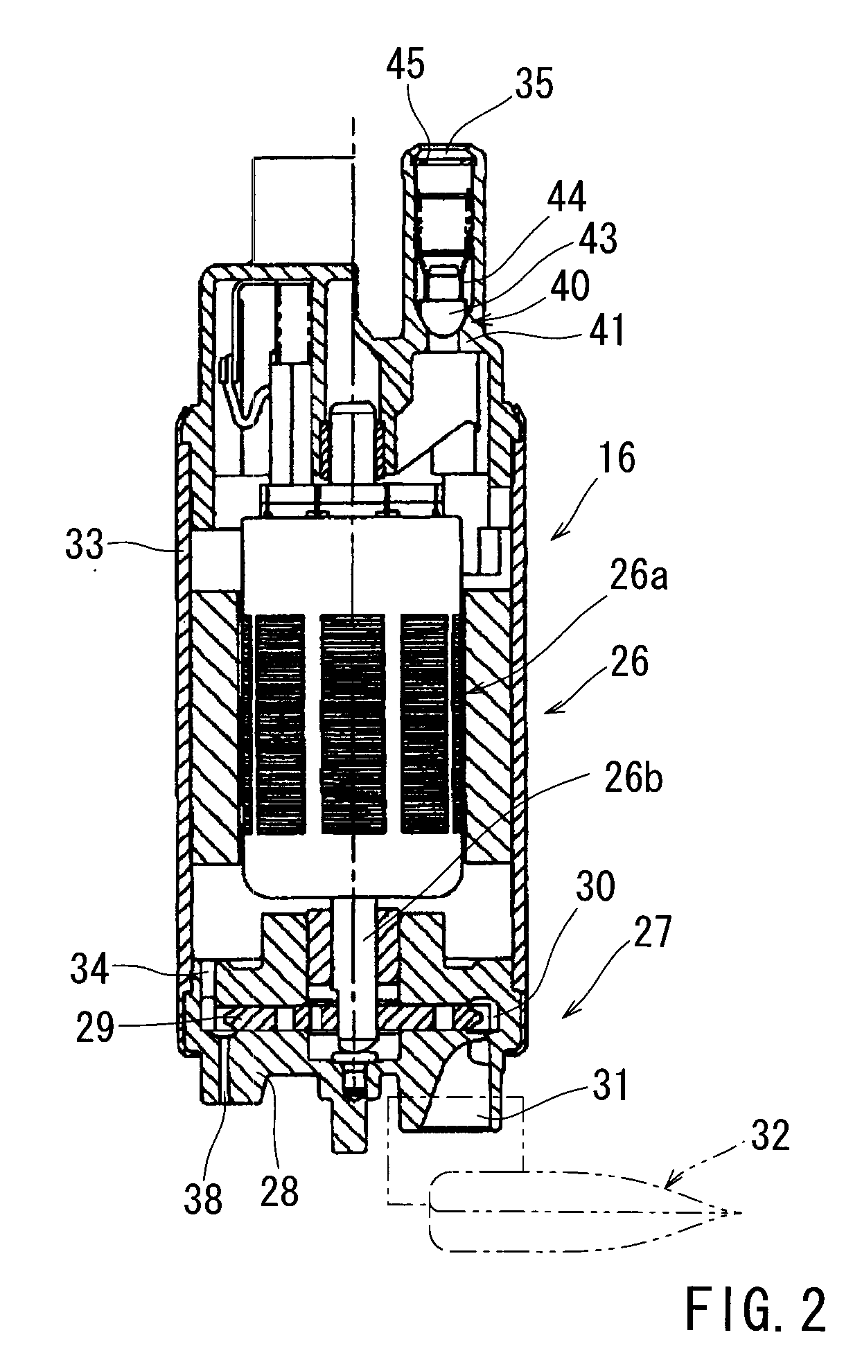
[0017]A first embodiment of the present invention will be described with reference to FIGS. 1 and 2. This embodiment of the present invention is directed to a fuel-feeding device for use in a vehicle engine.

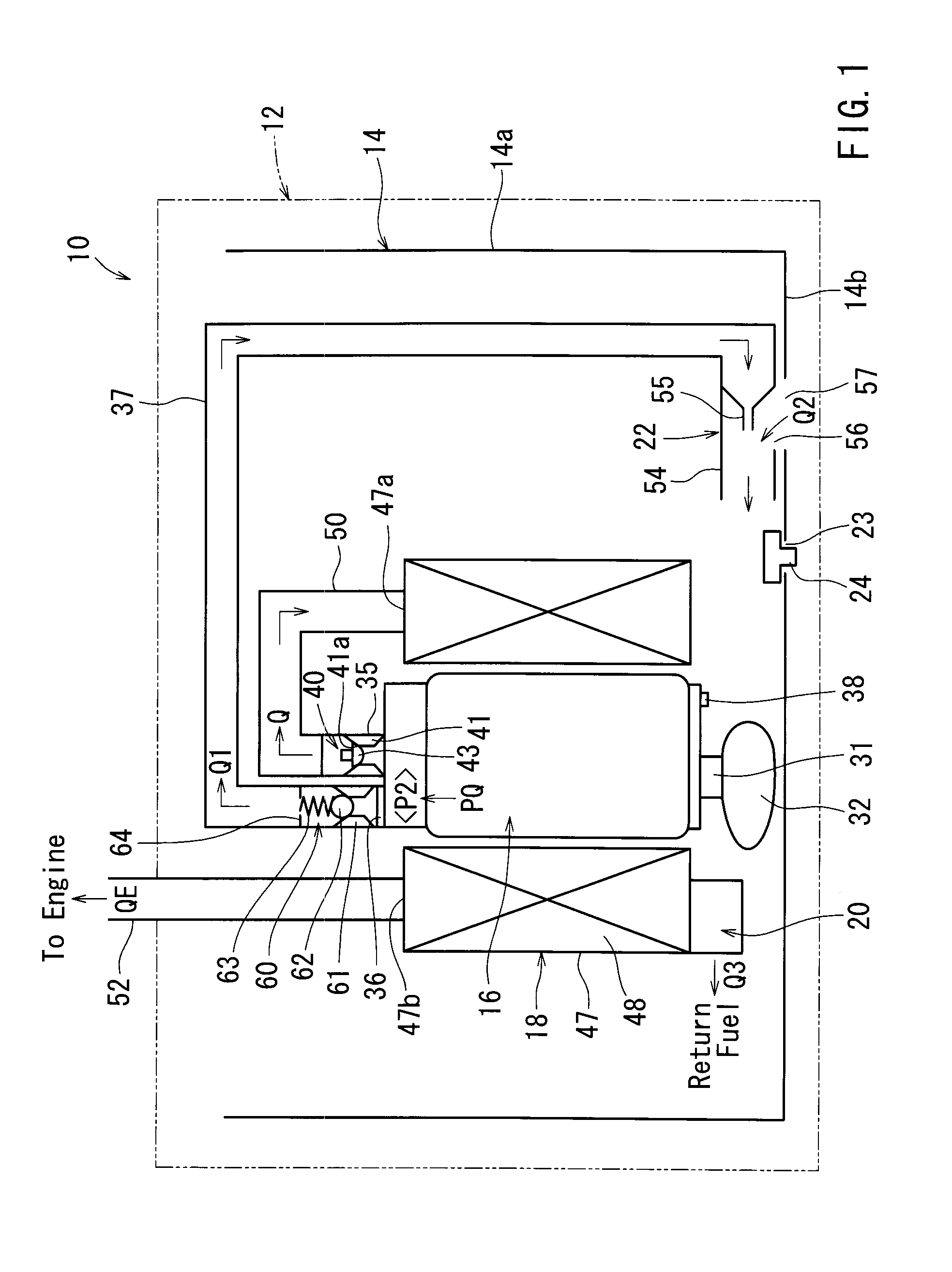
[0018]As shown in FIG. 1, the fuel-feeding device 10 may preferably be disposed in a fuel tank 12 of a vehicle (not shown) in which liquid fuel is contained. The fuel-feeding device 10 may preferably include a reservoir cup 14, an immersion type fuel pump 16 capable of feeding (pumping) the liquid fuel contained in the fuel tank 12 to an engine (not shown), a fuel filter 18, a pressure regulator 20 capable of controlling a pressure (i.e., a fuel pressure) of the liquid fuel fed to the engine, and a jet pump 22. The pressure regulator 20 is attached to the fuel pump 16.

[0019]The reservoir cup 14 (which may be referred to as a reservoir container or a sub-tank) may preferably be positioned on a bottom surface of the fuel tank 12. The reservoir cup 14 may preferably have a cylindric...

second embodiment

[0050]The second detailed representative embodiment will now described with reference to FIGS. 3 to 5.

[0051]Because the second embodiment relates to the first embodiment, only the constructions and elements that are different from the first embodiment will be explained in detail. Elements that are the same in the first and second embodiments will be identified by the same reference numerals and a detailed description of such elements may be omitted.

[0052]In a fuel-feeding device 110 of this embodiment, as shown in FIG. 3, the second outlet port 36 in the first embodiment is omitted. Instead, the vapor jet port 38 communicates with the jet pump 22 via the fuel jet conduit pipe 37. That is, the fuel jet path (the fuel jet conduit pipe 37) is substantially branched from the pump cavity 30 (a portion of the fuel feeder path) of the fuel pump 16. Further, in this embodiment, the vapor jet port 38 constitutes the branching portion of the fuel jet path.

[0053]Further, as shown in FIG. 4, a ...


PUM


Abstract

A fuel-feeding device may preferably include a reservoir cup disposed in a fuel tank that contains liquid fuel therein, a fuel pump capable of feeding the liquid fuel contained in the reservoir cup to an engine, a pressure regulator capable of controlling a fuel pressure of the liquid fuel fed to the engine from the fuel pump, a jet pump arranged and constructed to receive a part of the pressurized liquid fuel pumped from the fuel pump via a fuel jet path, so as to introduce liquid fuel outside the reservoir cup into to the reservoir cup with the aid of flow of the pressurized liquid fuel, and a flow rate control valve disposed in the fuel jet path. The flow rate control valve is arranged and constructed to control a flow rate of the pressurized liquid fuel fed to the jet pump depending upon a pumping rate of the pressurized liquid fuel pumped from the fuel pump.

Description

[0001]This application claims priority to Japanese patent application serial number 2007-320659, the contents of which are incorporated herein by reference.BACKGROUND OF THE INVENTION[0002]The present invention relates to a fuel-feeding device for feeding liquid fuel contained in a fuel tank of an automobile to an automobile engine (an internal-combustion engine).[0003]A fuel-feeding device is taught by, for example, Japanese Laid-Open Patent Publication No. 2005-69171. This fuel-feeding device includes a reservoir cup disposed in a fuel tank, a fuel pump capable of feeding (pumping) liquid fuel contained in the fuel tank to an engine via a feeding port, a pressure regulator capable of controlling a pressure of the liquid fuel fed to the engine (i.e., a fuel pressure), and a jet pump. The jet pump is arranged and constructed to inject the pressurized liquid fuel pumped from a relief port of the fuel pump into the reservoir cup, thereby introducing (drawing) the liquid fuel outside o...

Claims


Application Information

Patent Timeline
Patent Type & Authority Applications(United States)
IPC IPC(8): F02M37/04F02M69/54F04B49/22
CPCF02M37/0029F02M37/0058F02M2037/225F02M37/106F02M37/20F02M37/025F02M37/44
Inventor HONDA, YOSHIHIKOINOUE, TOMOAKIYOSHIDA, KOJI
Owner AISAN IND CO LTD
Why Eureka
Try Eureka