Hole Inspection Apparatus and Hole Inspection Method using the Same

a technology for semiconductor devices and via holes, applied in semiconductor/solid-state device testing/measurement, material analysis using wave/particle radiation, instruments, etc., can solve the problems of reducing the accuracy of data about the holes, reducing the danger of damage to samples, and reducing the time taken

Inactive Publication Date: 2009-06-18
CEBT
View PDF3 Cites 16 Cited by
  • Summary
  • Abstract
  • Description
  • Claims
  • Application Information

AI Technical Summary

Benefits of technology

[0016]The hole inspection apparatus according to the present invention can reduce the time taken to inspect holes, formed in the insulating layers, using a plurality of electron beam irradiation means.
[0017]Furthermore, in the case where the electron beam irradiation means are used as a microcolumn, a plurality of electron beams having low energy can be used, so that the danger of damage to a sample is reduced. Furthermore, in the case where the electron columns are used, image data about holes formed in the insulating layer can also be acquired using a scanning function, so that more accurate data about the holes can be acquired.
[0018]Furthermore, information about the depths, locations and shapes of respective holes, as well as information about whether holes are open at both ends thereof and images of the respective holes, can be acquired using the plurality of electron columns, so that holes formed at incorrect locations can be detected.
[0019]Furthermore, correction can be made such that holes are opened at both ends thereof using electron beams, so that it is possible to conduct repairs using a product targeted to inspection.

Problems solved by technology

However, this technology was proposed to solve a problem in which, when inspection for via holes is conducted using existing Scanning Electron Microscope (SEM) equipment, the openings of the respective via holes can be detected but information about the bottom sides of the respective via holes cannot be known.
However, the conventional hole inspection apparatus, described above, is problematic in that a lot of time is taken because an electron gun 2 that generates a single electron beam is used.
That is, in the case where a large number of holes must be inspected, although the respective holes are precisely inspected, a lot of time is taken, because the holes must be individually inspected.

Method used


Image

  • Hole Inspection Apparatus and Hole Inspection Method using the Same
  • Hole Inspection Apparatus and Hole Inspection Method using the Same
  • Hole Inspection Apparatus and Hole Inspection Method using the Same

Examples


Embodiment Construction

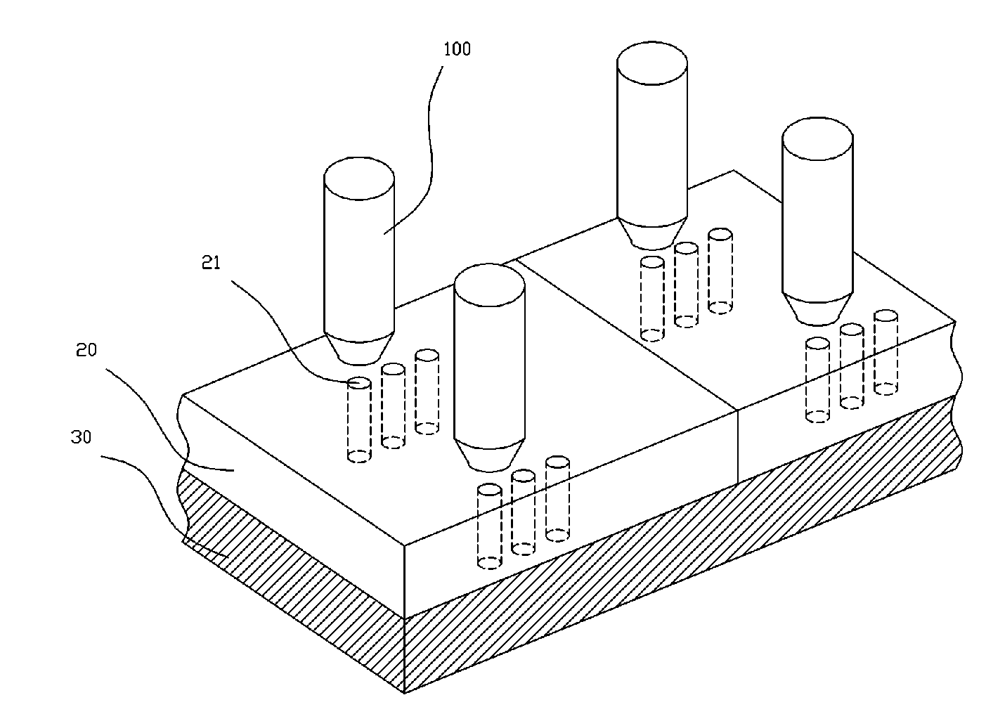
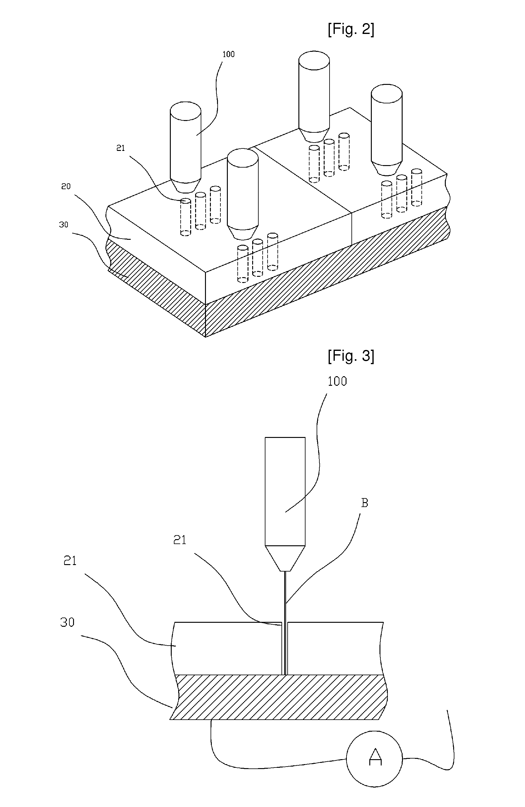
[0027]FIG. 2 is a perspective view schematically showing a hole inspection apparatus according to the present invention.

[0028]In FIG. 2, four electron columns 100 are used as electron beam irradiation means. For each of description, each electron column 100 is described as irradiating an electron beam across three holes 21. The holes 21 are formed in an insulating layer 20. A conductive layer 30 is located under the insulating layer 20. In this case, the three holes 21 to be inspected by each electron column 100 are formed in the insulating layer 20. Although the number of holes 21 and the size and shape of each hole have been set for the sake of description of the inspection apparatus according to the present invention, the number of holes 21 and the size and shape of each hole may be variously determined.

[0029]As shown in FIG. 2, the insulating layer 20 is divided into two regions, and the conductive layer 30 located under the insulating layer 20 is formed of a single layer. Accor...


PUM

PropertyMeasurementUnit
sizeaaaaaaaaaa
currentaaaaaaaaaa
depthsaaaaaaaaaa

Abstract

Disclosed herein is an apparatus and method for inspecting the via holes of a semiconductor device using electron beams. The apparatus includes electron beam irradiation means, a current measuring means, and a current measuring means and data processing means. The electron beam irradiation means radiate respective electron beams to inspect a plurality of inspection target holes. The current measuring means measures current, which is generated by irradiating the electron beams, radiated from the electron beam irradiation means, through a conductive layer located under the holes, or through the conductive layer and a separate detector. The data processing means processes data acquired through the measurement of the current measuring means.

Description

TECHNICAL FIELD[0001]The present invention relates, in general, to an apparatus and method for inspecting the via holes of a semiconductor device using electron beams and, more particularly, to an apparatus and method for inspecting the via holes of a semiconductor device in a relatively short time, which cause a plurality of electron beams, radiated from a plurality of electron beam generation means, to pass through the semiconductor device, thus measuring current.BACKGROUND ART[0002]Generally, a semiconductor device, such as memory, includes contact holes or via holes to electrically connect active elements, which are formed in the lower portion thereof, to wiring layers, which are formed in the upper portion thereof. The contact holes are formed by etching an insulating layer, such as an oxide layer, from the surface thereof to a lower substrate using Reactive Ion Etching (RIE). In order to optimize etching conditions, it is required that the internal and external structure of ea...

Claims


Application Information

Patent Timeline
Patent Type & Authority Applications(United States)
IPC IPC(8): G01N23/00
CPCG01R31/307H01J37/244H01J37/28H01J2237/0635H01J2237/22H01J2237/244H01L22/14H01J2237/24592H01J2237/281H01J2237/2817H01J2237/317H01L22/12H01J2237/24564H01L22/00
Inventor KIM, HO SEOB
Owner CEBT
Why Eureka
Try Eureka