
Child restraint apparatus for vehicle

a child seat and vehicle technology, applied in vehicle components, pedestrian/occupant safety arrangements, vehicle arrangements, etc., can solve the problems of sudden deceleration of the child seat, injury to the occupant of the car seat, and injury to the side of the body of the passenger sitting adjacent to the child sea

Active Publication Date: 2009-06-18
BRITAX CHILD SAFETY
View PDF14 Cites 84 Cited by
  • Summary
  • Abstract
  • Description
  • Claims
  • Application Information

AI Technical Summary

Benefits of technology

[0010]The above mentioned needs and others that will be readily apparent to those skilled in the art are met by the invention, which in one aspect provides a child restraint apparatus for restraining a child within a vehicle interior. The apparatus has a body comprising an internal area for receiving a child, and an energy absorbing member which, in use, extends over at least part of an external surface of the body and which faces away from the internal area. The energy absorbing member seeks to cushion an impact that may occur with a passenger adjacent the child restraint apparatus in the event of a crash and thereby reduce the likelihood of injury to the passenger.
[0011]Optionally, the energy absorbing member comprises a deformable chamber. A deformable chamber allows the energy absorbing member to be deflated allowing the child restraint apparatus to be more readily stored. The chamber then need only be deployed when the child restraint apparatus is installed in a vehicle.
[0013]Optionally, the chamber is provided with open cell foam. Open cell foam is a readily available material which may be easily formed to the required configuration and which provides resilient, controlled air release characteristics.
[0017]Optionally, the energy absorbing member is attached to the outer side edge of the child restraint apparatus along one edge of the said energy absorbing member. In this way, the energy absorbing member can be folded away from the outer side edge of the child restraint apparatus to assist with inflation or deflation of the energy absorbing member or to conceal an orifice or vent.
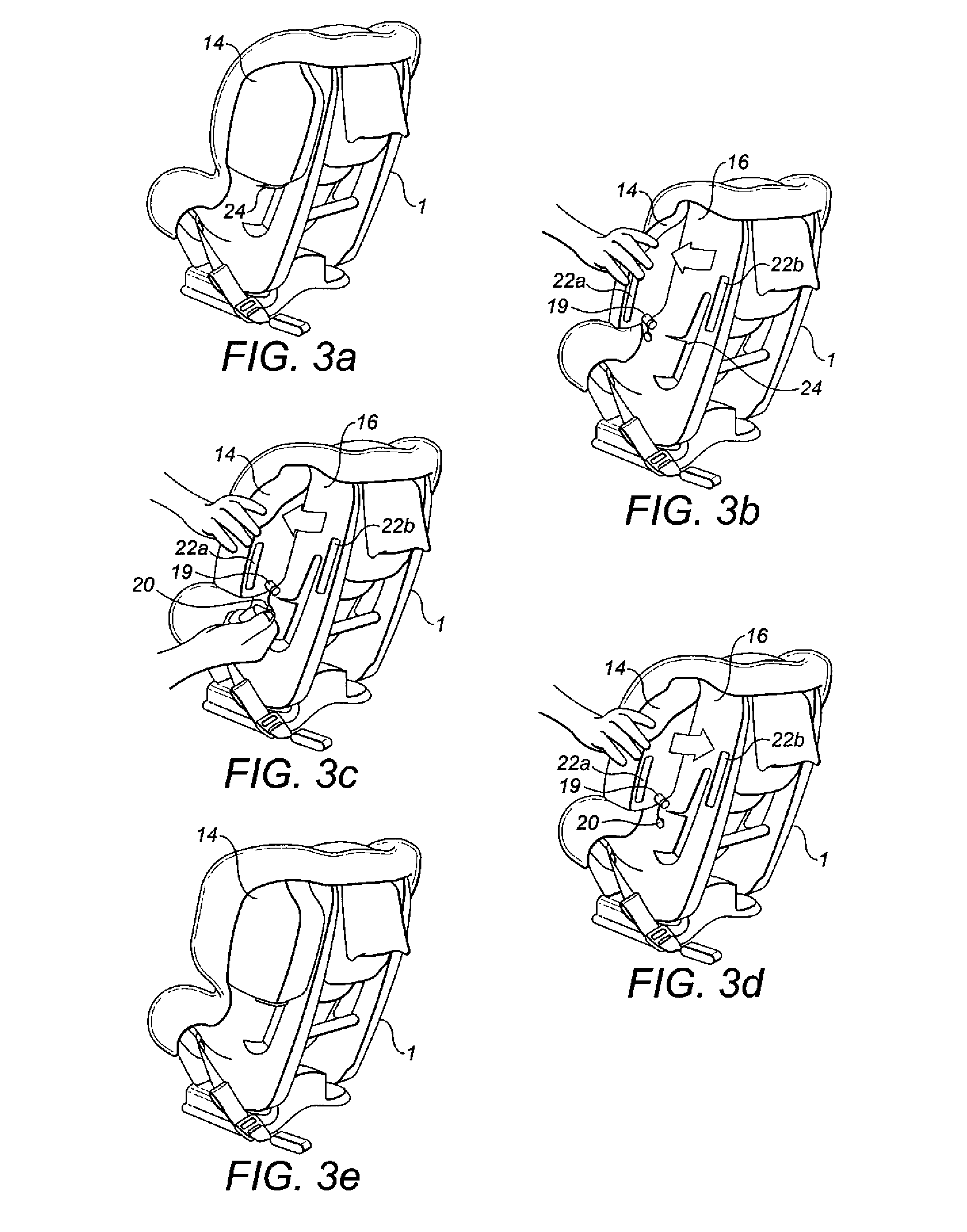
[0018]According to a further aspect of the present invention there is provided a method of operating a child restraint apparatus within a vehicle, the apparatus having an externally positioned energy absorbing member in the form of a vented deformable chamber, the method comprising the steps of providing the child restraint apparatus in a vehicle interior with the chamber collapsed and the vent closed, then with the child restraint apparatus in position in vehicle, opening the vent such that air enters the chamber, the vent thereafter being left open so as to provide controlled venting in the event of a deformation of the chamber as a result of an accident. The energy absorbing member need only be deployed when the child restraint apparatus is installed in a vehicle, thereby allowing the child restraint apparatus to be more easily stored and handled.

Problems solved by technology

Consequently, a passenger sitting adjacent the child seat may themselves suffer injury to the side of their body, including the torso, arms and / or upper leg areas, depending on the shape of the child car seat and where precisely the child car seat impacts the passenger.
In addition to injury that may be caused to an adjacent passenger, the impact of the child car seat on the adjacent passenger may also cause a sudden deceleration to the child car seat.
This sudden deceleration may in turn cause injury to the occupant of the car child seat, as a result of the potentially high forces exerted in particular on the child seat occupant=s head and neck.
If the side impact of the vehicle should however occur on the opposite side of the vehicle, i.e. when the child car seat is positioned furthest from the point of impact on the rear seat of a vehicle, then there is a risk that the adjacent passenger to the child car seat will in this instance move towards the child car seat.
Again there is a risk that the adjacent passenger will be injured as a result of impact with the child car seat, for example injury to the pelvis.
Similarly, the occupant of the child car seat, due to the sudden impact, may be subjected to unduly high forces in particular to the occupant=s head and neck.
Furthermore, the impact of the adjacent passenger with the child car seat may also in turn result in the child car seat impacting with the interior side of the vehicle and causing further injuries to the occupant of the child car seat.

Method used


Image

  • Child restraint apparatus for vehicle
  • Child restraint apparatus for vehicle
  • Child restraint apparatus for vehicle

Examples


Embodiment Construction

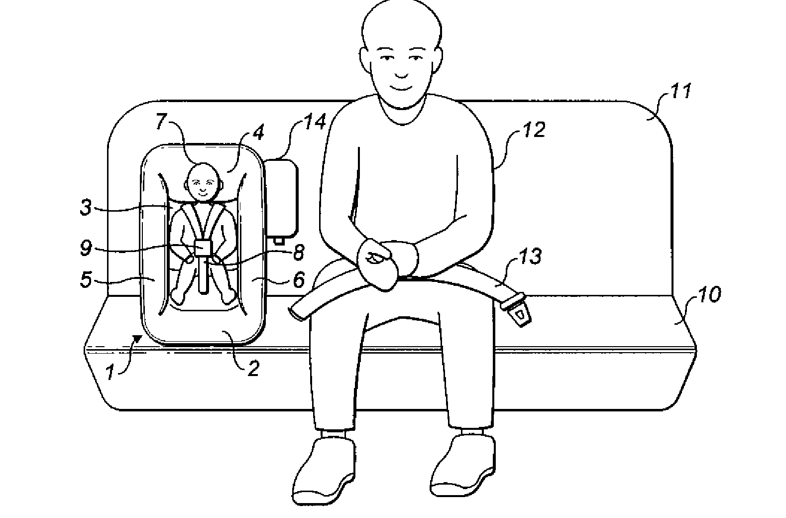
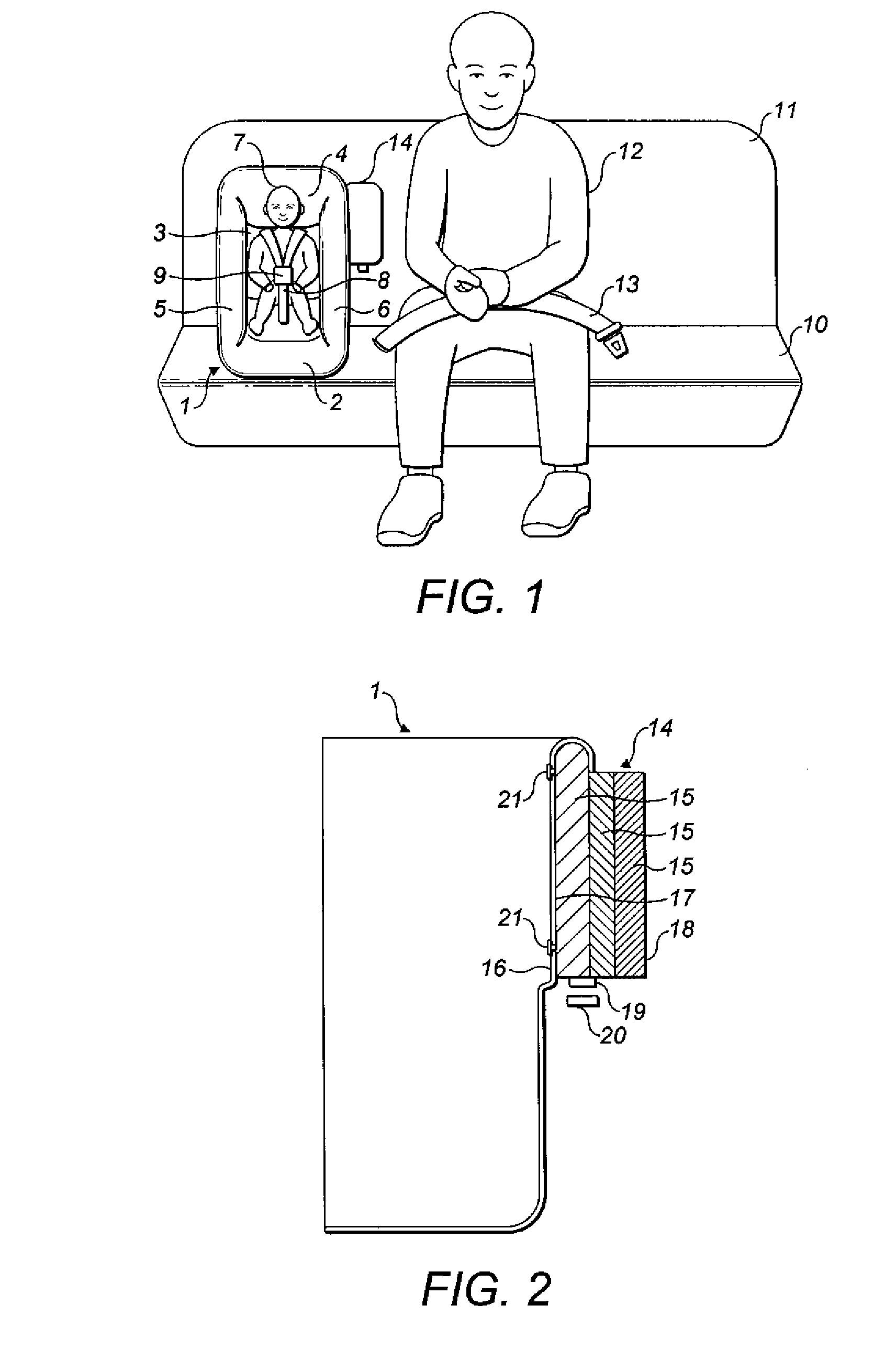
[0026]FIG. 1 shows a child restraint apparatus in the form of a child car seat shown generally as 1. The child car seat 1 comprises a seat portion 2, a back portion 3, a head portion 4 and side portions 5,6 to form a substantially rigid shell or body portion which partially surrounds the occupant 7 of the child car seat. The body comprises an internal area for receiving a child and the car seat 1 is further provided with an adjustable safety harness 8 and a buckle 9 which serves to restrain the child 7 in the seat 1.

[0027]In the embodiment shown in FIG. 1, the child car seat 1 is located on the right side of a rear seat bench 10 of a vehicle with respect to the direction of travel. In the embodiment shown, the occupant of the child car seat is facing forwardly, i.e. away from the rear vehicle seat back 11. The child car seat is attached by means of an Isofix type connection (not shown). When in position, the child seat 1 takes up the area of one rear vehicle cushion, thereby leaving...


PUM


Abstract

A child restraint apparatus relates to holding a child within a vehicle interior. The apparatus has a body with an internal area for receiving a child. An energy absorbing member extends in use over at least part of an external surface of the body. This energy absorbing member faces away from the internal area.

Description

BACKGROUND OF THE INVENTION[0001]The present invention relates to a child restraint apparatus for example a child car seat for use in a vehicle. In particular, the present invention concerns such apparatus for reducing the risk of injury to passengers present in the vehicle who are seated adjacent said child car seat in the event of a vehicle accident or the like.[0002]In this connection, it is well known to provide child car seats to carry children and infants safely in vehicles. Most commonly, the child car seat is located on the rear seat of a vehicle and is attached or restrained to the vehicle seat using a connection which makes use of a standard vehicle seat belt or dedicated connection points such as lower anchors, top tethers or those of the Isofix type. That said, child car seats may also be located on a front passenger seat of a vehicle, in which case, the child car seat is usually attached using the front passenger seat belt.[0003]When located on the rear seat of a vehicl...

Claims


Application Information

Patent Timeline
Patent Type & Authority Applications(United States)
IPC IPC(8): B60N2/42
CPCB60N2/2884B60N2/2881B60N2/4235
Inventor AMESAR, PANKAJ TULSIDASMAHAL, BARRYDOWNIE, DAVID GARDINERPITCHER, MARK ROBERTCARINE, DAVID SHAUNHANKINSON, CHRISTOPHER
Owner BRITAX CHILD SAFETY
Learn More