Smart key system using lf antennas of tpms

Inactive Publication Date: 2009-06-18
HYUNDAI MOTOR CO LTD
View PDF9 Cites 31 Cited by
  • Summary
  • Abstract
  • Description
  • Claims
  • Application Information

AI Technical Summary

Benefits of technology

[0019]Accordingly, the present invention has been made keeping in mind the above problems occurring in the prior art, and an object of the present invention is to pr

Problems solved by technology

However, although all the antennas 23, 24, and 25, used for the smart key system, and the LF antennas 33, used for the TPMS, use the same frequency and the configurations of the

Method used


Image

  • Smart key system using lf antennas of tpms
  • Smart key system using lf antennas of tpms
  • Smart key system using lf antennas of tpms

Examples


Embodiment Construction

[0030]Reference now should be made to the drawings, in which the same reference numerals are used throughout the different drawings to designate the same or similar components.

[0031]A smart key system using LF antennas of a TPMS (hereinafter referred to as ‘smart key system’) according to embodiments of the present invention will be described in detail with reference to the attached drawings below.

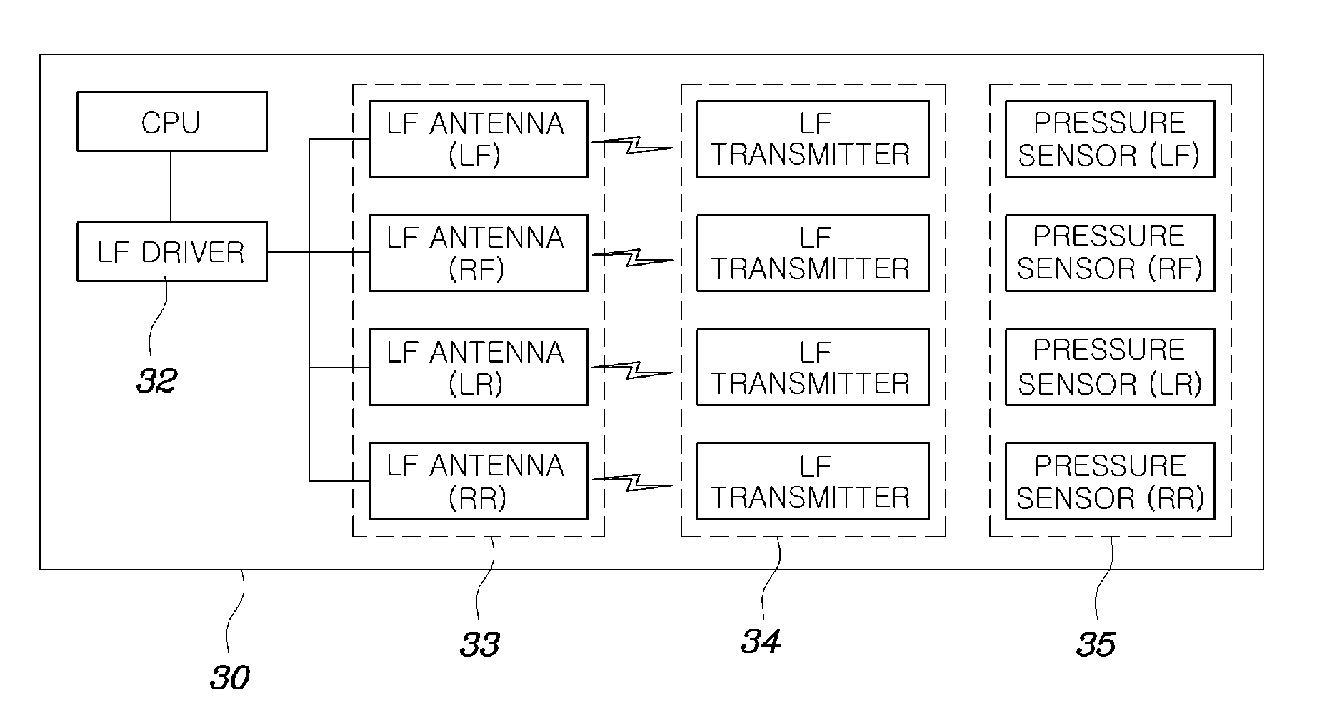
[0032]FIG. 4 is a block diagram showing the configuration of the smart key system according to an embodiment of the present invention.

[0033]As shown in FIG. 4, a smart key system 100 includes a CPU 102 for controlling the operation of locking a door and detecting tire pressure, and first and second LF drivers 104 and 106 for transmitting / receiving signals used to operate the respective systems thereof. Of course, the first and second LF drivers 104 and 106 may be implemented as an integrated low frequency driver.

[0034]In FIG. 4, the first LF driver 104 is used to operate the smart key syst...


PUM


Abstract

The present invention provides a smart key system using Low Frequency (LF) antennas of a Tire Pressure Monitoring System (TPMS), in which a Central Processing Unit (CPU) installed inside a vehicle control locking modules of respective doors to be opened or locked in response to an open/close signal from a smart key configured to transmit/receive a wireless signal unique to the vehicle. A plurality of antennas are installed on the vehicle for receiving a low frequency control signal transmitted from the smart key. One or more of the antennas are the LF antennas used for the TPMS of the vehicle.

Description

CROSS-REFERENCE TO RELATED APPLICATIONS[0001]This application claims under 35 U.S.C. §119(a) priority to Korean Application No. 10-2007-0129288, filed on Dec. 12, 2007, the disclosure of which is incorporated herein by reference in its entirety.BACKGROUND[0002]1. Technical Field[0003]The present invention relates generally to a smart key system, and, more particularly, to a smart key system in which Low Frequency (LF) antennas of a Tire Pressure Monitoring System (TPMS) can be used for the smart key system.[0004]2. Background Art[0005]With the improvement in the standard of living, the popularization of privately owned cars has increased, and thus privately owned cars have established themselves as life necessities. Therefore, research into devices for preventing vehicles, including privately owned cars, from being stolen, and into various techniques for opening the doors of a vehicle and starting the engine of the vehicle has been steadily conducted. Examples include a keyless entr...

Claims


Application Information

Patent Timeline
IPC IPC(8): B60C23/00
CPCB60C23/0408B60R25/245G07C2009/00793G07C9/00309G07C9/00944E05B77/48E05B49/00
Inventor KIM, EUN HEE
Owner HYUNDAI MOTOR CO LTD
Why Eureka
Try Eureka