Device and method for alignment of binocular personal display

a personal display and binocular technology, applied in the field of binocular optical systems, can solve the problems of large personal display devices, incompatible personal displays, and large suitable mechanisms for aligning and maintaining binocular alignment over different ipds, and achieve the effect of maintaining a compact structure and high alignment accuracy

Active Publication Date: 2009-06-18
LUMUS LTD
View PDF8 Cites 145 Cited by
  • Summary
  • Abstract
  • Description
  • Claims
  • Application Information

AI Technical Summary

Benefits of technology

[0005]It is an object of the present invention to provide a personal binoc...

Problems solved by technology

Relatively small misalignment can lead to serious user discomfort, headaches, nausea, and, in extreme cases, symptoms of sea-sickness and other ailments.
Suitable mechanisms for aligning and maintaining the binocular alignment over different IPDs are relatively large and incompatible with personal displays, which are required to be compact.
Many different methods have been devised for binocular alignment, however, so far, some propos...

Method used


Image

  • Device and method for alignment of binocular personal display
  • Device and method for alignment of binocular personal display
  • Device and method for alignment of binocular personal display

Examples


Embodiment Construction

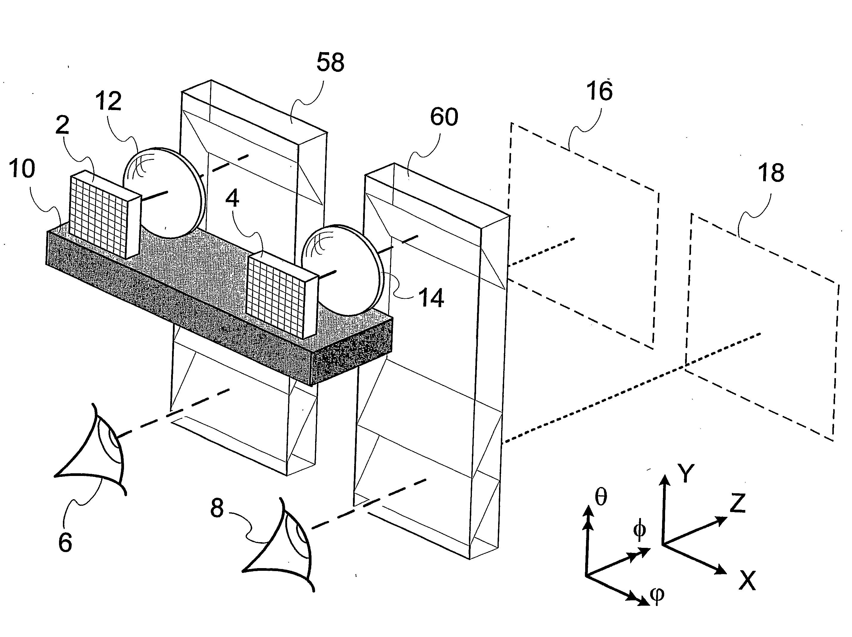
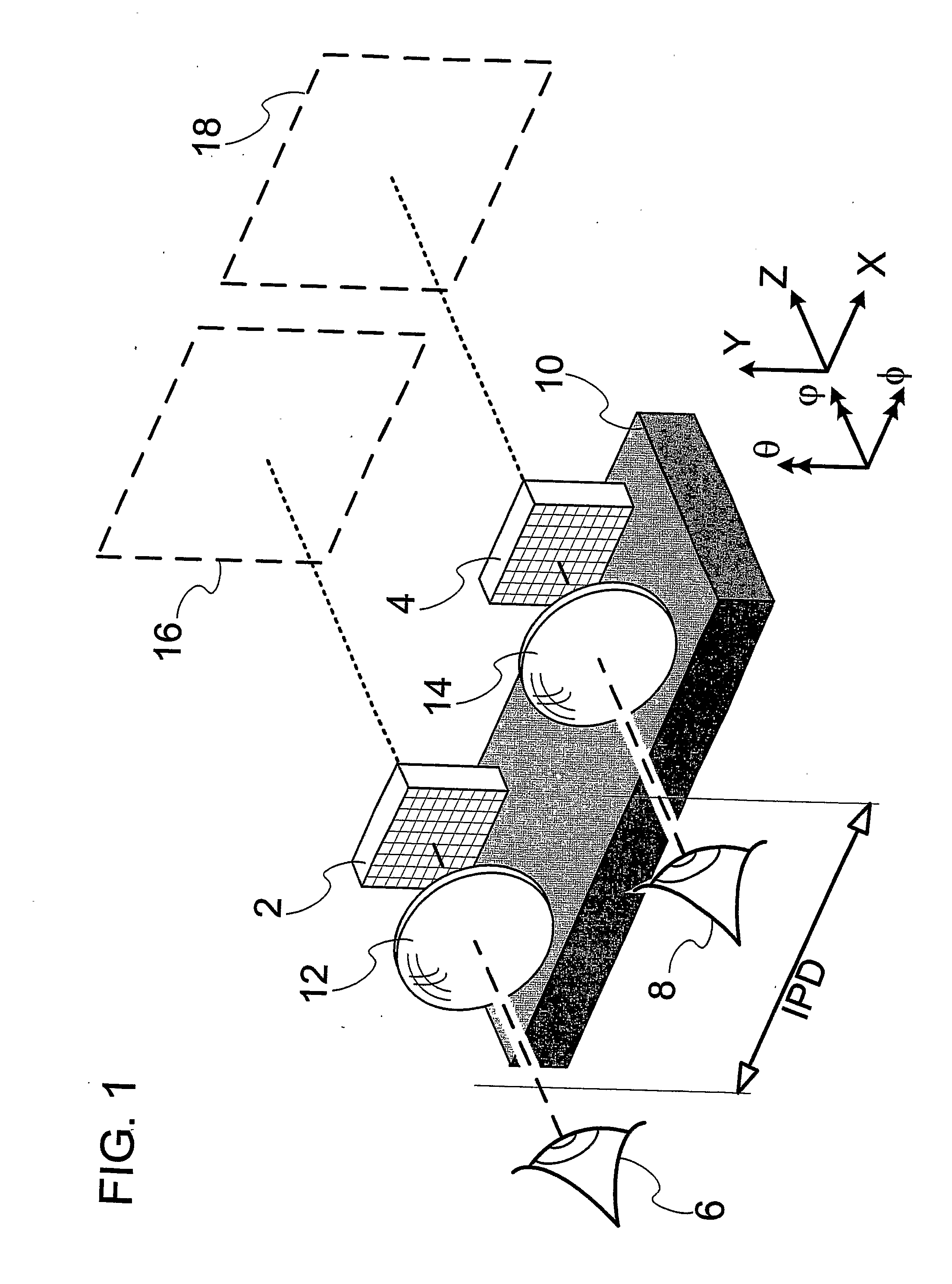
[0021]FIG. 1 schematically illustrates a typical binocular personal device, including two image sources 2, 4, one for the left eye 6, and one of the right eye 8 of an observer, mounted on a rigid mechanical body 10. Two magnifying lensing devices 12, 14, are also mounted onto the same mechanical body 10, one for magnifying the left image source 2, and one for magnifying the right image source 4. The lensing devices 12, 14 may be embodied by common lenses, reflection lenses, diffractive optics such as holograms, combinations thereof, or any other image magnifying devices, with or without folding optics for compressing its size. The lensing devices generate two virtual images, 16 and 18 to be viewed, respectively, by the left eye 6 and the right eye 8. The coordinate system, illustrated in the right hand side of the figure, defines the axes as follows: the linear axes Z in the direction of the line-of-sight to the image, and X and Y in the lateral directions. The rotational axes θ, a ...


PUM


Abstract

There is provided a binocular device, including a rigid mechanical body supporting two image sources (2, 4), one for each eye (6, 8) and two lensing devices (12, 14), one for each eye, the lensing devices having a first surface adjacent to the image sources and an opposite, second surface, each of the lensing devices projecting an image (16, 18) of one image source onto an infinite focal plane, and electronic means permitting modification of an image generated to an eye for adjusting the binocular alignment of the images. A method for aligning a binocular device is also provided.

Description

FIELD OF THE INVENTION[0001]The present invention relates to binocular optical systems, and in particular, to binocular devices and methods of alignment thereof.[0002]The invention can be implemented to advantage in binocular personal display applications, including two-dimensional and three-dimensional views with or without see-through capabilities. The word “binocular” as used herein refers to an optical device suitable for viewing with two eyes. The more common use of “binocular” as short-hand for “binocular telescope” is referred to herein as “Binoculars”.BACKGROUND OF THE INVENTION[0003]Personal displays are growing in importance with increasing proliferation of mobile and wearable communication, information and entertainment devices, in addition to their more traditional applications for simulators, mixed reality and other head-mounted applications. In many situations a binocular personal display system is preferred to a monocular personal display system for its superior conve...

Claims


Application Information

Patent Timeline
IPC IPC(8): G09G5/00
CPCG02B6/0018G02B7/12G02B27/0172G02B2027/0178G02B2027/0132G02B2027/0138G02B2027/014G02B2027/0129
Inventor AHARONI, ABRAHAM
Owner LUMUS LTD
Why Eureka
Try Eureka