
Liquid crystal display element, method of driving the element, and electronic paper having the element

Inactive Publication Date: 2009-06-18
FUJITSU LTD
View PDF9 Cites 12 Cited by
  • Summary
  • Abstract
  • Description
  • Claims
  • Application Information

AI Technical Summary

Benefits of technology

[0051]According to the invention, a driving voltage and a pulse width of the voltage are varied at each step for displaying gray levels by utilizing cumulative response characteristics of a liquid crystal. Specifically, there is provided a first step for changing the reflectance of a liquid crystal layer to a first reflectance value that is either of two predetermined reflectance values to obtain a first gray level and a second step for changing the reflectance of the liquid crystal layer to a second reflectance value lower than the first reflectance value to obtain a second gray level lower than the first gray level. Thus, driving voltages can be kept low to allow the use of inexpensive general-purpose drivers providing binary output and having a low withstand voltage.
[0052]At the second step, a region having great margins of intermediate gray levels (the intermediate gray level region A in FIG. 4) is used. Therefore, high quality multi-level display can be achieved with quite small granularity.
[0053]The amount of data required for displaying an image can be minimized even when the number of gray levels is increased.

Problems solved by technology

However, those schemes for dynamic driving have the problem of high granularity in halftones, although they allow high speed driving.
In general, dynamic driving necessitates a dedicated driver capable of providing a multiplicity of voltage outputs, and the manufacture of such a driver and the complicatedness of a control circuit for the driver can be significant sources of a cost increase.
However, the method is not expected to eliminate high granularity that is a problem with dynamic driving.
The driving method still leaves the concern about granularity of intermediate tones unsolved, and the method has another problem in that a product cannot be manufactured in an inexpensive configuration because a high driving voltage is required.
Therefore, the driving methods result in images having high granularity although they allow high speed driving, and a problem still therefore remains in display quality.
798-801, 1998), and the method also has a problem.
However, since the method allows driving a relatively high rate, a drive voltage as high as 50 to 70 V is required, which can result in a cost increase.
Such an approach results in a problem in display quality.
That is, a great amount of image data in proportion to the number of gray levels is required.

Method used


Image

  • Liquid crystal display element, method of driving the element, and electronic paper having the element
  • Liquid crystal display element, method of driving the element, and electronic paper having the element
  • Liquid crystal display element, method of driving the element, and electronic paper having the element

Examples


Embodiment Construction

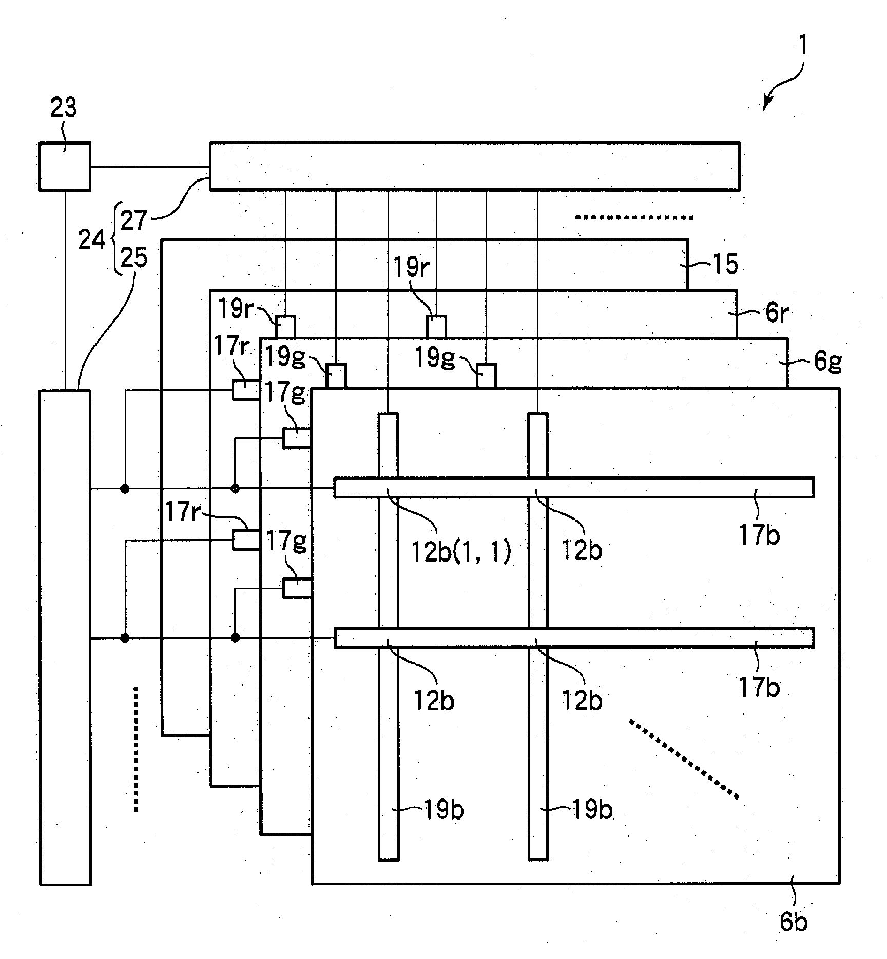
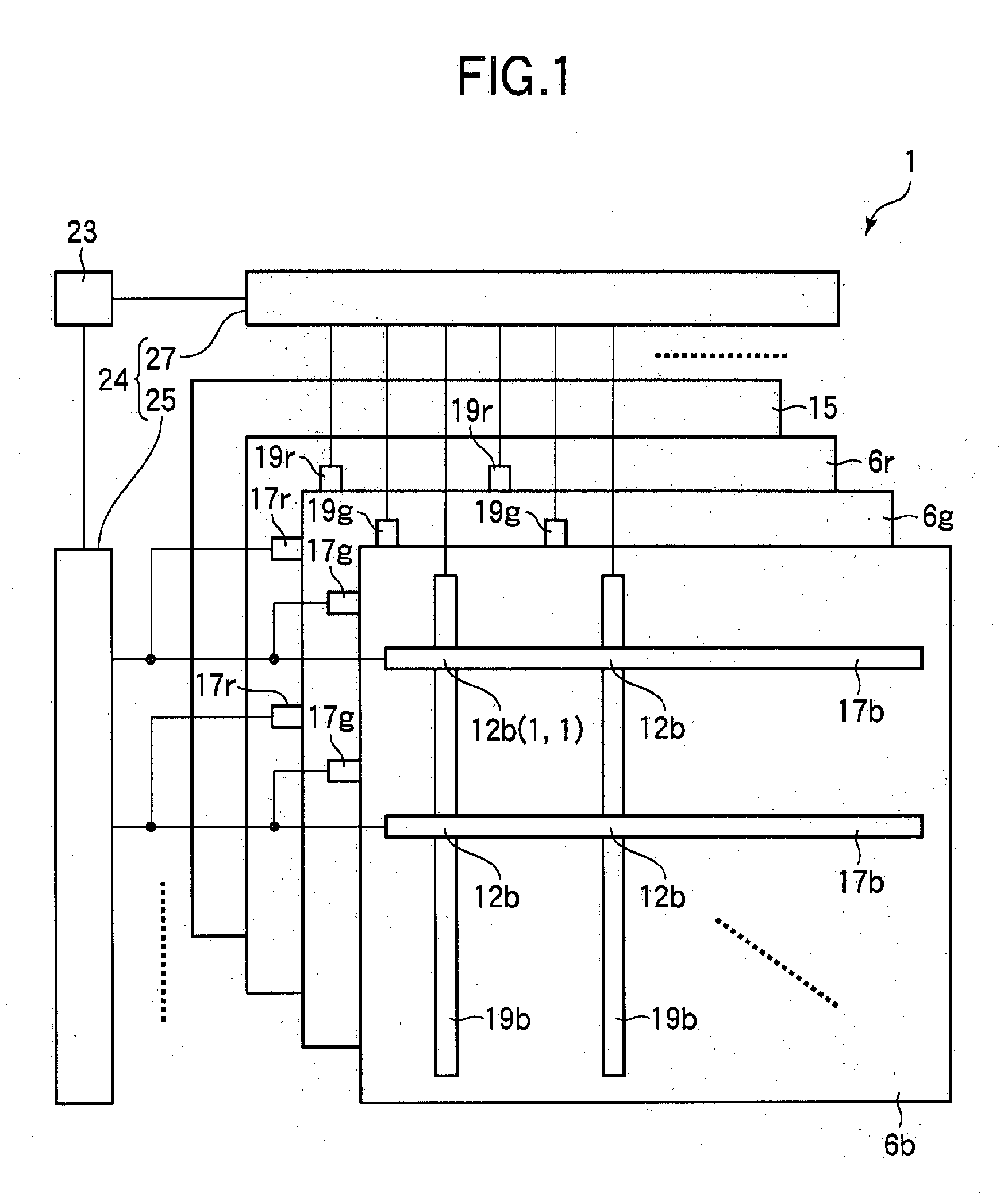
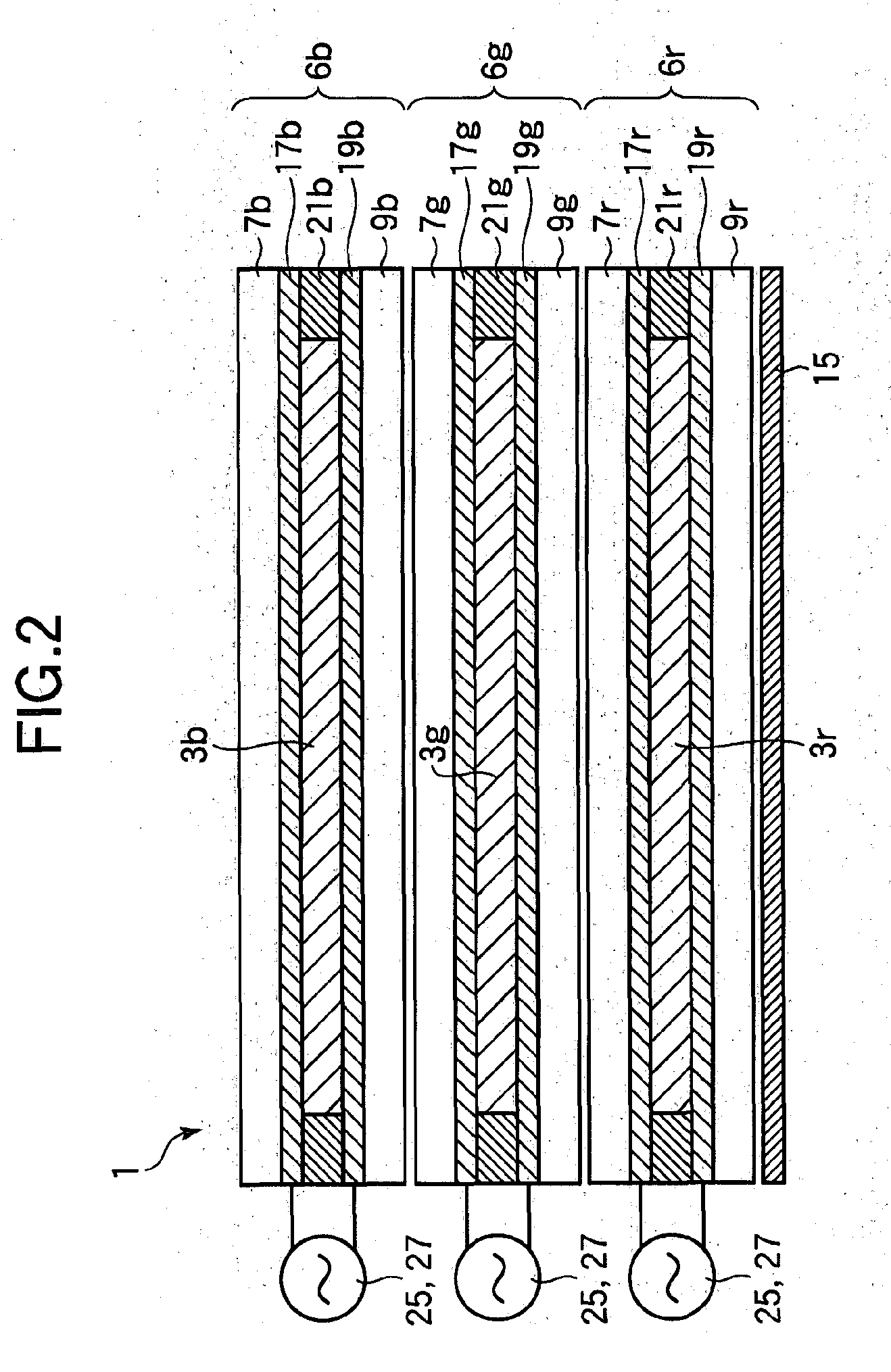
[0084]A liquid crystal display element, a method of driving the element, and electronic paper having the element according to an embodiment of the invention will now be described with reference to FIGS. 1 to 24. A liquid crystal display element 1 utilizing cholesteric liquid crystals for blue (B), green (G), and red (R) will be described as an example of an embodiment of the invention. FIG. 1 shows a schematic configuration of the liquid crystal display element 1 of the present embodiment. FIG. 2 is a schematic view of a sectional configuration of the liquid crystal display element 1 taken along a straight line extending in parallel with the horizontal direction of FIG. 1.

[0085]As shown in FIGS. 1 and 2, the liquid crystal display element 1 includes a B display portion (first display portion) 6b for selectively reflecting blue (B) light as a selected wave band in the planar state, a G display portion (second display portion) 6g for selectively reflecting green (G) light as another s...


PUM


Abstract

The invention relates to a liquid crystal display element for displaying an image by driving a liquid crystal and provides a liquid crystal display element capable of multi-level display of high display quality using general-purpose drivers, a method of driving the element, and electronic paper having the element. To display gray level “4”, a pulse voltage of ±32 V is applied at a first step to put a cholesteric liquid crystal in a planar state (level “7”)). Then, a pulse voltage of ±24 V is applied for 2.0 ms at a sub-step to the cholesteric liquid crystal to change the gray level to level “5” that is two steps lower. A pulse voltage of ±24 V is applied for 1.0 ms at another sub-step to cause a further transition of the cholesteric liquid crystal toward a focal conic state, thereby obtaining gray level “4” that is one step lower than level “5”.

Description

[0001]This application is a continuation of International Application No. PCT / JP2006 / 316528, filed Aug. 23, 2006.BACKGROUND[0002]1. Field[0003]The present invention relates to a liquid crystal display element which displays an image by driving a liquid crystal, a method of driving the element, and electronic paper having the element.[0004]2. Description of the Related Art[0005]Recently, various enterprises and universities are actively engaged in the development of electronic paper. The most promising application of electronic paper is electronic books, and other promising applications include portable apparatus such as mobile terminal sub-displays and display portions of IC cards. One type of display elements used in electronic paper is liquid crystal display elements utilizing a liquid crystal composition which forms a cholesteric phase (such a composition is referred to as “cholesteric liquid crystal” or “chiral nematic liquid crystal” and the term “cholesteric liquid crystal” wi...

Claims


Application Information

Patent Timeline
IPC IPC(8): G09G3/36G02F1/137
CPCG02F2001/13478G09G3/2014G09G3/2081G09G2310/062G09G2300/023G09G2300/0486G09G3/3629G02F1/13478
Inventor NOSE, MASAKI
Owner FUJITSU LTD
Learn More