
Fiber optic spectroscopic digital imaging sensor and method for flame properties monitoring

a fiber optic spectroscopic digital imaging and sensor technology, applied in the direction of optical radiation measurement, instruments, sensing radiation from gases/flames, etc., can solve the problems of difficult to obtain reliable measurements, limited control methods, and several challenges to measurement inside the combustor or gasification reactor vessel, so as to minimize the impact of purging gas, reduce the effect of affecting reducing the effect of oxidation

Active Publication Date: 2009-06-18
THE BOARD OF TRUSTEES OF THE UNIV OF ILLINOIS
View PDF9 Cites 6 Cited by
  • Summary
  • Abstract
  • Description
  • Claims
  • Application Information

AI Technical Summary

Benefits of technology

[0009]It is one object of this invention to provide a system for flame properties monitoring in a combustor or gasifier which is capable of characterizing the overall combustor or gasifier performance.
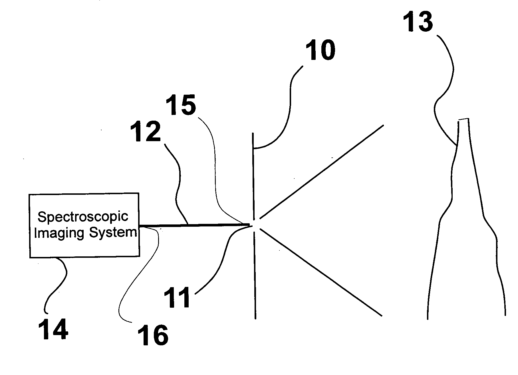
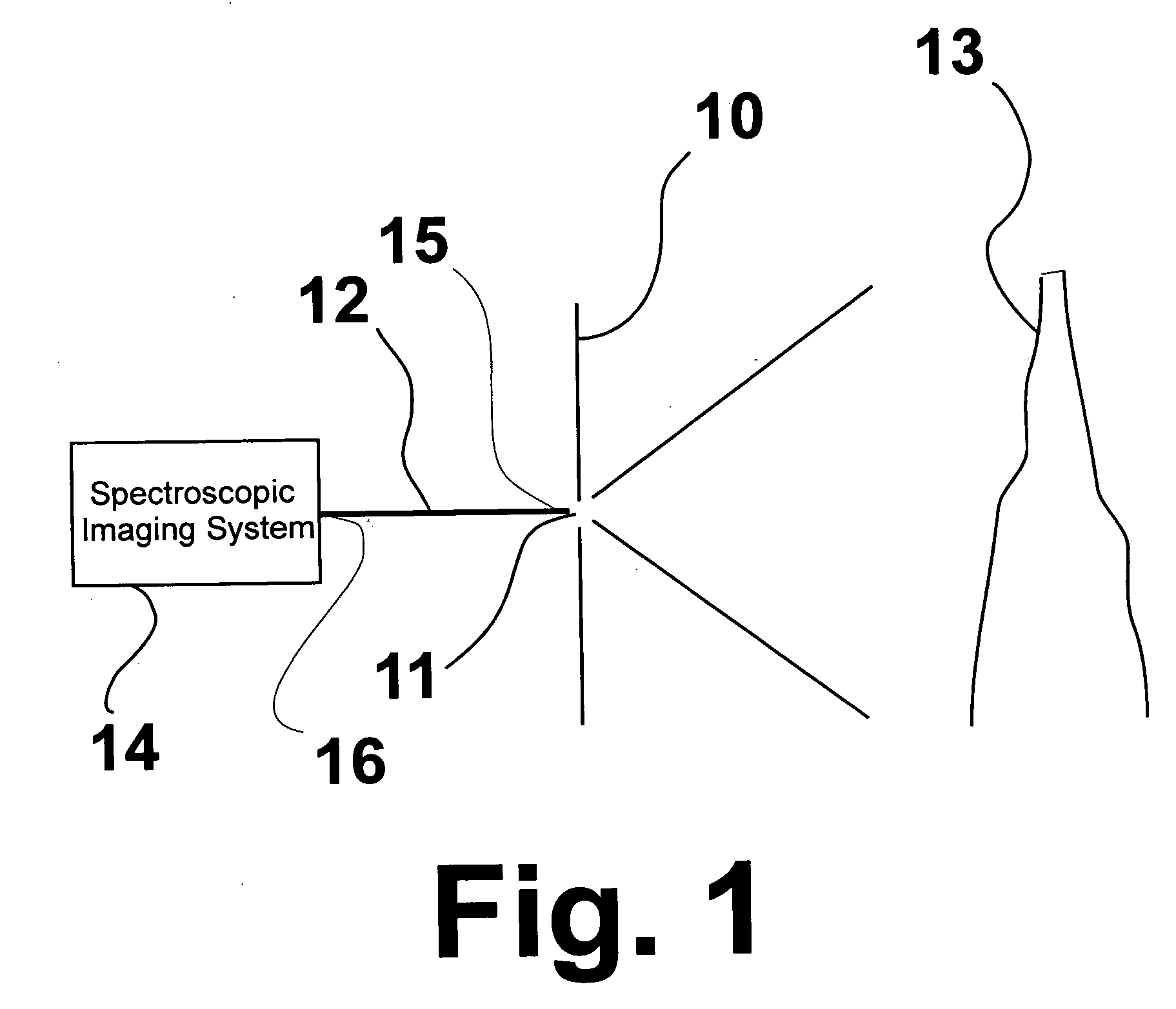
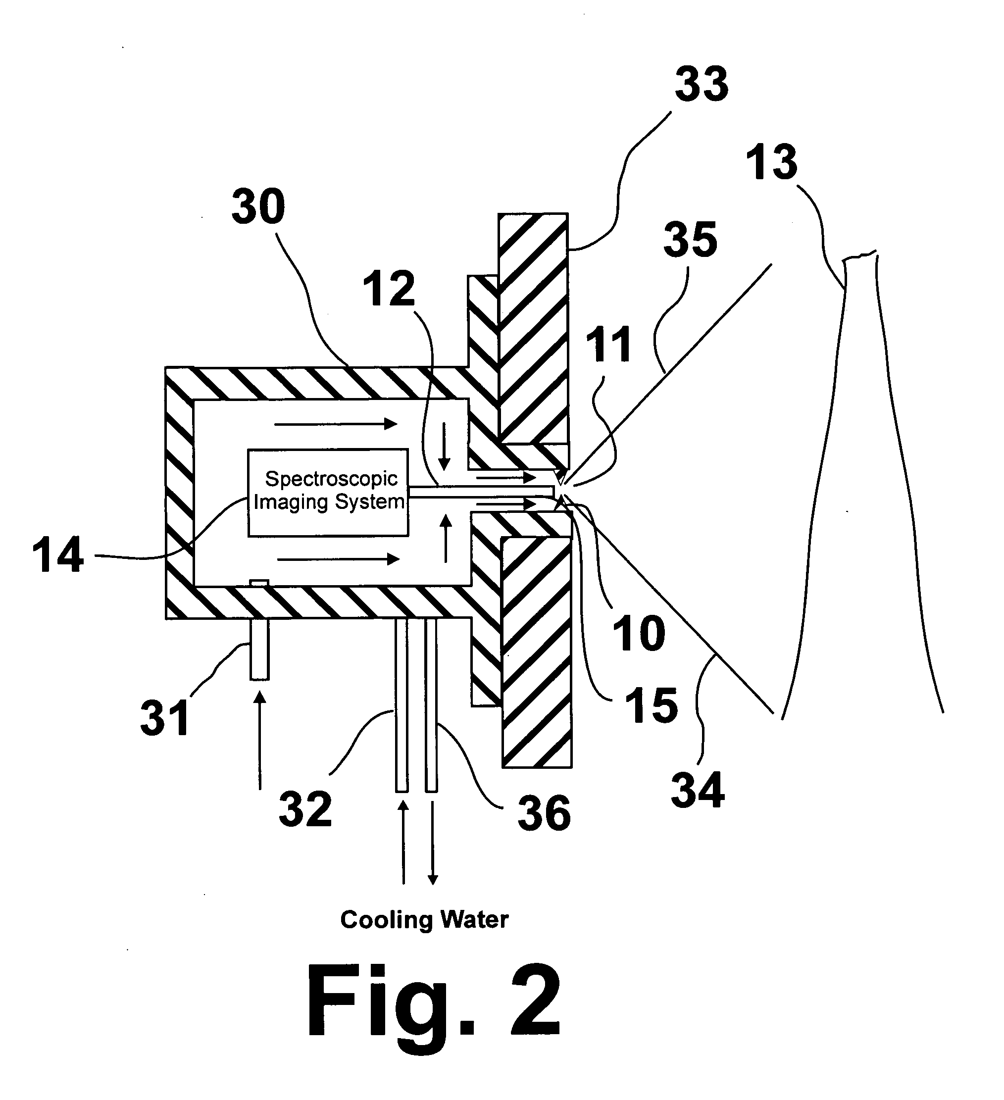
[0012]These and other objects of this invention are addressed by a sensor comprising an imaging fiber optic bundle coupled with a spectroscopic imaging system employing an imaging monochromator and intensified CCD camera. In accordance with one embodiment of this invention, the input plane of the imaging fiber optic bundle is positioned in the refractory of a combustor or gasifier reactor vessel wall in close proximity of the inner reactor cavity of the combustor or gasifier reactor vessel, thereby providing a wide observation angle. The light emitted from various locations within the combustor or reactor vessel is collected by the fiber optic bundle and transmitted as an image to the spectroscopic imaging system where the emitted light can be analyzed to provide spectrally-resolved light intensities in the ultra-violet and visible region. Unique to the system of this invention is the use of a pinhole-sized observation port through which the light from within the combustor or gasifier passes to be collected by the fiber optic bundle. Use of the pinhole-sized observation port or opening provides a means for focusing the flame light onto the fiber optic bundle entrance, thereby obviating the placement of a lens or any other optics between the fiber optic bundle and the flame light. In addition, when using a purging gas, the pinhole-sized opening produces a high velocity low mass flow of purging gas so as to minimize the impact of the purging gas on the combustion or gasification process as well as limit any effects that the purging gas may have on the measurement process. The system further comprises a secondary purging arrangement providing tangential purging with a preheated gas so as to minimize cooling effects and, as a result, frozen slag deposition on the sensor components and refractory.

Problems solved by technology

Present control methods are mostly limited to the measurement of global system parameters such as output product compositions and emission levels or to the measurement of parameters which provide only limited information regarding the overall processes.
Measurements performed inside the flame zone using thermocouples or optical pyrometers generally provide only point or line-of-sight information that is insufficient for characterizing the overall combustor performance.
However, such processes present several challenges to measurements inside the combustor or gasification reactor vessels.
However, slag on the walls of the gasifier must be traversed by the probe if measurements are to be made within the interior of the gasifier.
In addition, reliability of the measurements is difficult to obtain due to the harsh environment inside the gasifier in the form of dust particles, etc., which tend to obscure the temperature measuring device such that measurements therein may not be obtainable at all or, if obtainable, may be distorted.

Method used


Image

  • Fiber optic spectroscopic digital imaging sensor and method for flame properties monitoring
  • Fiber optic spectroscopic digital imaging sensor and method for flame properties monitoring
  • Fiber optic spectroscopic digital imaging sensor and method for flame properties monitoring

Examples


Embodiment Construction

[0024]FIG. 1 is a schematic representation of the salient features of the system of this invention. As shown therein, the system comprises a wall 10 having a pinhole opening 11. Imaging fiber optic bundle 12 having a light receiving end 15 and a light output end 16 is disposed on one side of wall 10 with the flame 13 to be monitored disposed on the opposite side of wall 10. Light receiving end 15 of the imaging fiber optic bundle is aligned with pinhole opening 11. Pinhole opening 11 acts to focus the flame image received by the light receiving end of the fiber optic bundle. As used herein, the term “pinhole” refers to openings having a diameter in the range of about 1 μm to about 1 mm. In accordance with one particularly preferred embodiment of this invention, pinhole opening 11 has a diameter in the range of about 10 μm to about 100 μm. Unexpectedly, the use of a pinhole opening obviates the need for focusing lenses, protective windows, or any other object intervening between the ...


PUM


Abstract

A system for real-time monitoring of flame properties in combustors and gasifiers which includes an imaging fiber optic bundle having a light receiving end and a light output end and a spectroscopic imaging system operably connected with the light output end of the imaging fiber optic bundle. Focusing of the light received by the light receiving end of the imaging fiber optic bundle by a wall disposed between the light receiving end of the fiber optic bundle and a light source, which wall forms a pinhole opening aligned with the light receiving end.

Description

[0001]The U.S. Government has a paid-up license in this invention and the right in limited circumstances to require the patent owner to license others on reasonable terms as provided for by the terms of Contract No. DE-FC26-02NT41585 awarded by the U.S. Department of Energy.BACKGROUND OF THE INVENTION[0002]1. Field of the Invention[0003]This invention relates to a method and apparatus for monitoring the properties of flames in high pressure combustors and gasifiers in real time. More particularly, this invention relates to a sensor for real-time monitoring of flame properties using fiber optic spectroscopic digital imaging. Although intended for use in connection with pressurized combustors and gasifiers, the method and apparatus of this invention may be employed in any combustion apparatus in which slagging occurs or in which the environment of the combustion process is particle- and / or particulate-laden, i.e. a “dirty” or “dusty” environment, including processes at about atmospher...

Claims


Application Information

Patent Timeline
IPC IPC(8): G01J3/00
CPCG01J3/02G01J5/602G01J3/0286G01J3/2823G01J5/0014G01J5/0018G01J5/0044G01J5/02G01J5/029G01J5/041G01J5/048G01J5/061G01J5/08G01J5/0821G01J5/0856G01J5/522G01J3/0218G01J5/051G01J5/53
Inventor ZELEPOUGA, SERGUEI A.RUE, DAVID M.SAVELIEV, ALEXEI V.
Owner THE BOARD OF TRUSTEES OF THE UNIV OF ILLINOIS
Learn More