
X-ray tube whose electron beam is manipulated synchronously with the rotational anode movement

a technology of x-ray tube and electron beam, which is applied in the direction of x-ray tube electrodes, electrical devices, electric discharge tubes, etc., can solve the problems of only possible stepwise switching of x-ray intensity and smearing of signals, and achieve the effect of simple mechanical setup

Inactive Publication Date: 2009-06-18
KONINKLIJKE PHILIPS ELECTRONICS NV
View PDF42 Cites 18 Cited by
  • Summary
  • Abstract
  • Description
  • Claims
  • Application Information

AI Technical Summary

Benefits of technology

The present invention provides an X-ray tube with a rotating anode and an electron beam manipulation device that can synchronize the electron beam with the anode movement. The electron beam manipulation device can be an electromagnetic force generation device or an electron beam dump. The use of an electron-focusing device can accurately control the focal spot of the X-rays generated from the X-ray tube. The invention allows for precise control of the electron beam in a synchronized manner with respect to the anode movement.

Problems solved by technology

All these measures have the disadvantage that the generation of a pulsed electron beam is based on applying relatively high alternating voltages or currents to various components of the X-ray tube.
However, all these components and also corresponding supply lines for these components have parasitic capacitances and impedances such that the corresponding voltage or current signals are smeared out.
Therefore, a stepwise switching of the X-ray intensity is only possible if costly voltage or current sources are employed for modulating the electron beam.

Method used


Image

  • X-ray tube whose electron beam is manipulated synchronously with the rotational anode movement
  • X-ray tube whose electron beam is manipulated synchronously with the rotational anode movement
  • X-ray tube whose electron beam is manipulated synchronously with the rotational anode movement

Examples


Embodiment Construction

[0080]The illustration in the drawing is schematically. It is noted that in different figures, similar or identical elements are provided with the same reference signs or with reference signs, which are different from the corresponding reference signs only within the first digit.

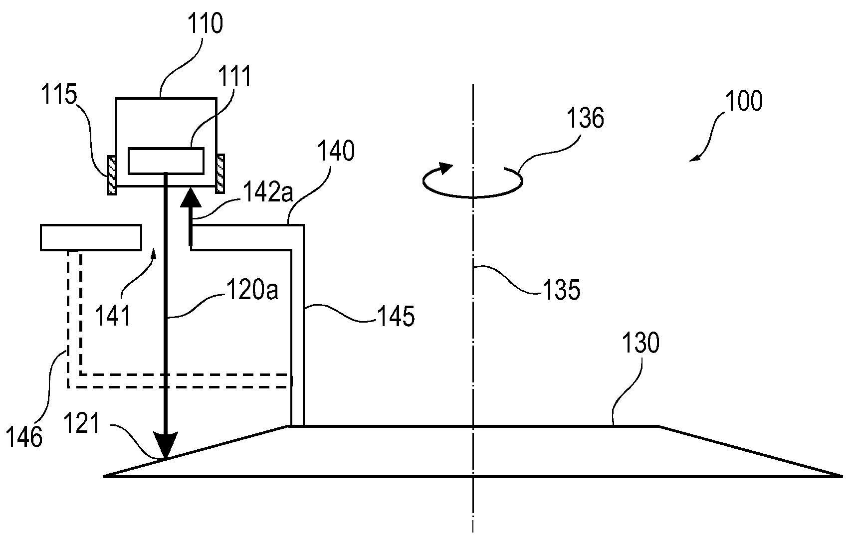
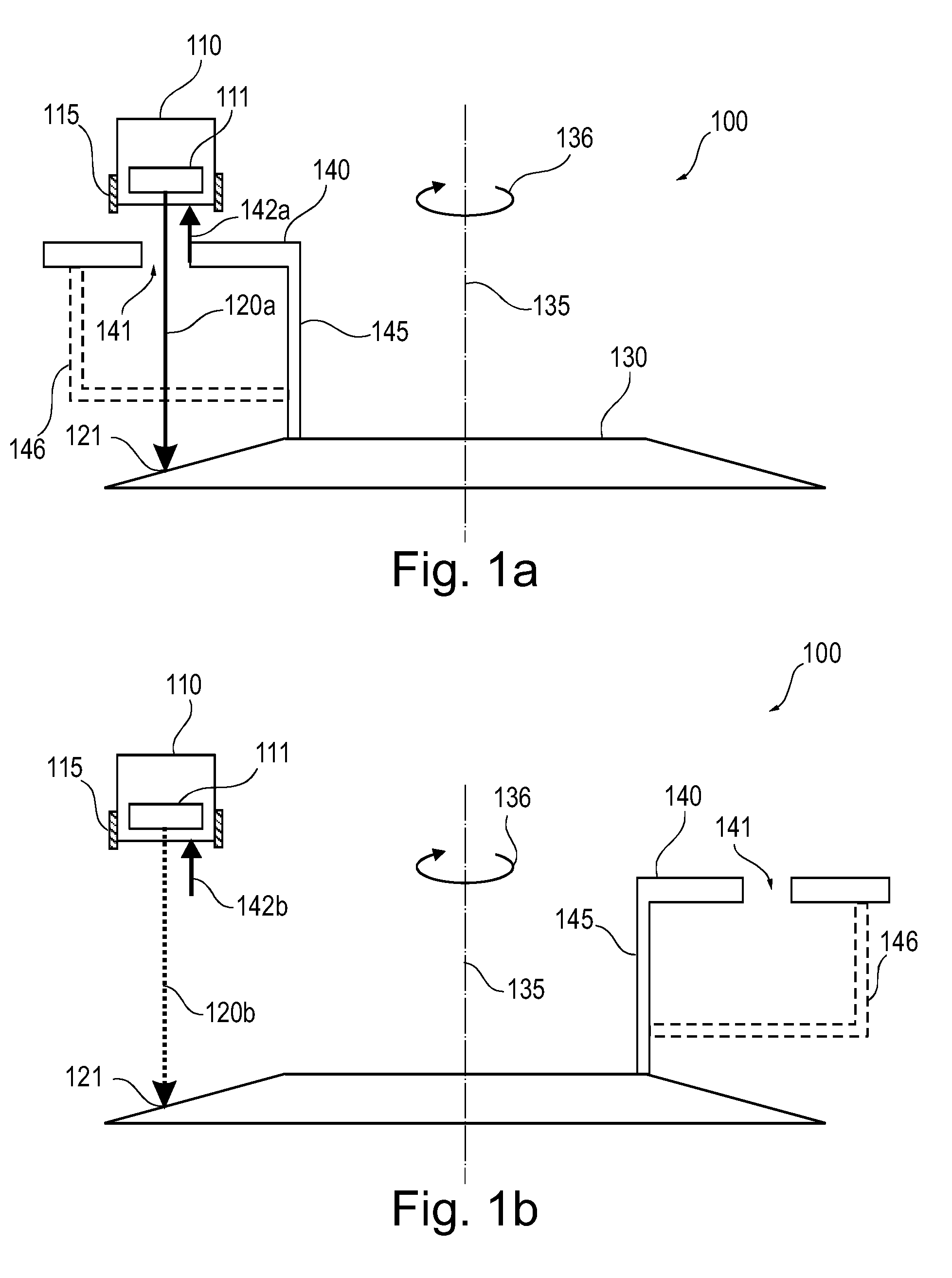
[0081]In the following the structure of an X-ray tube 100 representing a preferred embodiment of the invention is explained with reference to FIG. 1a and FIG. 1b. Thereby, FIG. 1a shows a cross sectional view of the X-ray tube 100 at a first point in time whereas FIG. 1b shows a cross sectional view of the X-ray tube 100 at a second point in time.

[0082]The X-ray tube 100 comprises an electron source 110. The electron source 110 includes a hot cathode 111 and an electron-focusing device 115, which is realized by means of a so-called wehnelt cylinder. When operated properly, the electron source 110 emits an electron beam 120a.

[0083]The X-ray tube 100 further comprises a rotatable anode 130, which has a rotati...


PUM


Abstract

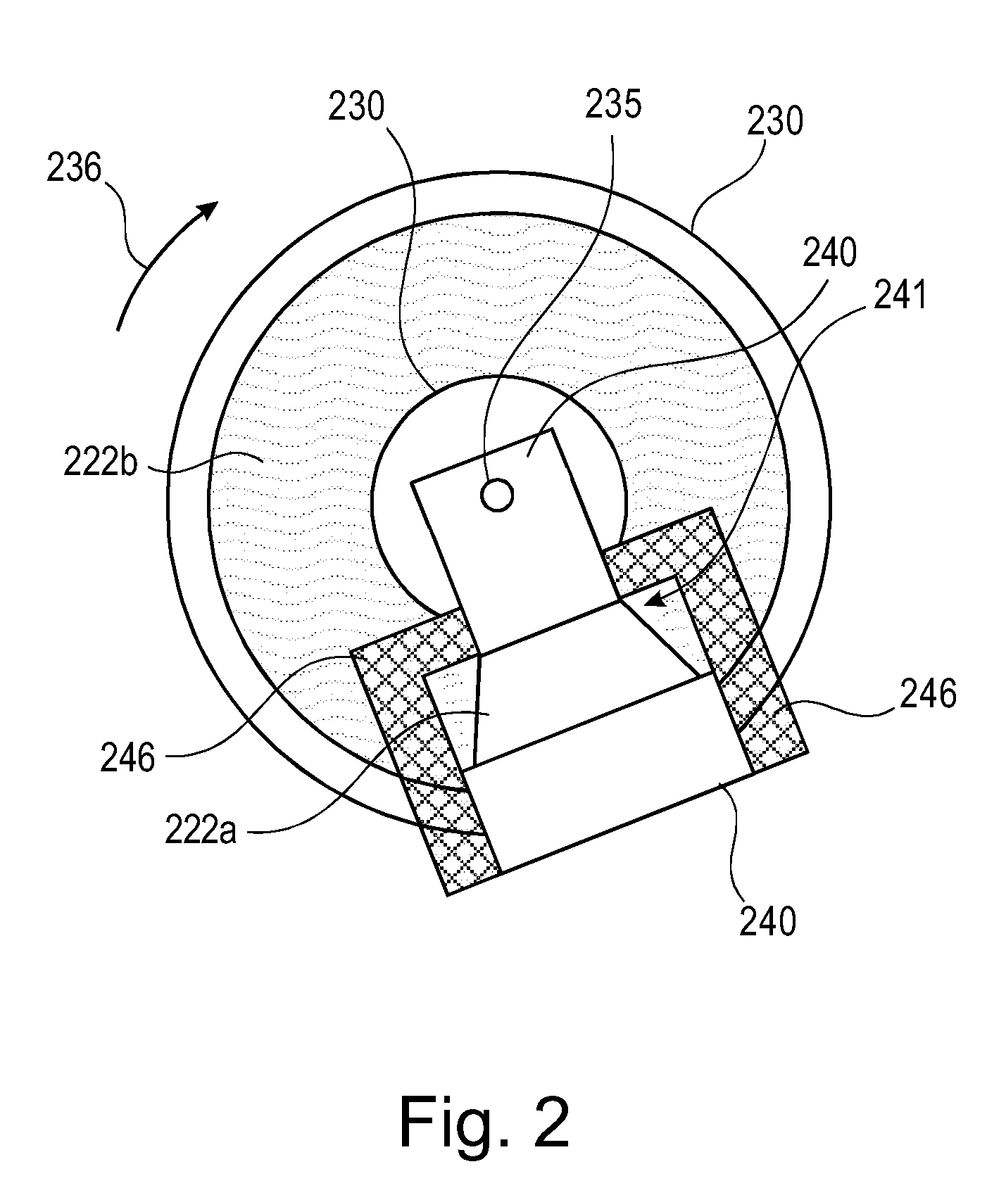
It is described an X-ray tube (100) comprising a rotating anode (130), which is provided with a pull electrode (140). The pull electrode (140) interacts with a fixed electron source (110) in order to generate a modulated electron beam (120a, 120b). The beam modulation may be an intensity variation and / or a spatial deflection. The pull electrode (140) is mounted in a fixed position with respect to the anode (130) and rotates together therewith. The pull electrode (140) may have a hole (141) for passing the electron beam (120a). When being in front of the electron source (110), the pull electrode (140) causes a high electric field (142a) such that a strong electron beam (120a) is generated. When being not in front of the electron source (110) only a low current or a zero current electron beam (120b) is generated. However, the pull electrode (740) may also cause a radial beam deflection such that depending on the angular position of the anode (730) the position of a focal spot (721a, 721b) of the electron beam (720) is varied.

Description

FIELD OF INVENTION[0001]The present invention relates to the field of generating X-rays by means of X-ray tubes. In particular, the present invention relates to an X-ray tube wherein an electron beam impinging onto an anode of the X-ray tube is periodically manipulated. Thereby, the manipulation may comprise a variation of the beam current such that the generated X-ray intensity may be modulated in time. The manipulation may also comprise a spatial variation such that a focal spot of the electron beam impinging onto the anode may be varied spatially.[0002]The present invention further relates to an X-ray system, in particular a medical X-ray imaging system, wherein the X-ray system comprises an X-ray tube as mentioned above.[0003]Further, the present invention relates to a method for generating X-rays, which are in particular used for medical X-ray imaging, wherein there is used an X-ray tube as mentioned above.ART BACKGROUND[0004]Computed tomography (CT) is a standard imaging techn...

Claims


Application Information

Patent Timeline
Patent Type & Authority Applications(United States)
IPC IPC(8): H01J35/30
CPCH01J35/10H01J35/305H01J35/14H01J35/147H01J35/153
Inventor BEHLING, ROLF KARL OTTO
Owner KONINKLIJKE PHILIPS ELECTRONICS NV
Learn More