
Unit with built-in control circuit

Inactive Publication Date: 2009-06-18
YAZAKI CORP
View PDF7 Cites 6 Cited by
  • Summary
  • Abstract
  • Description
  • Claims
  • Application Information

AI Technical Summary

Benefits of technology

[0011]The unit with a built-in control circuit according to the third aspect of the invention includes a conductive member formed integrally with the conductive connecting part thus reducing the number of parts.
[0012]As described above, the invention according to the first aspect of the invention supports changeovers to the specifications for a protective element by changing the protective elements attached to the terminals and the conductive connection part. This eliminates the need for modifying a circuit element even when the specifications for the protective element are changed. This prevents an increase in the product number of circuit elements and prevents an increase in the cost of a unit with a built-in control circuit.
[0014]The invention according to the third aspect of the invention includes a conductive member formed integrally with the conductive connecting part thus reducing the number of parts. This more reliably prevents an increase in the cost of a unit with a built-in control circuit.

Problems solved by technology

To respond to such changeover to the specifications, it is necessary to modify the circuit element itself which is likely to add to the cost of the connector with a built-in function.

Method used


Image

  • Unit with built-in control circuit
  • Unit with built-in control circuit
  • Unit with built-in control circuit

Examples


first embodiment

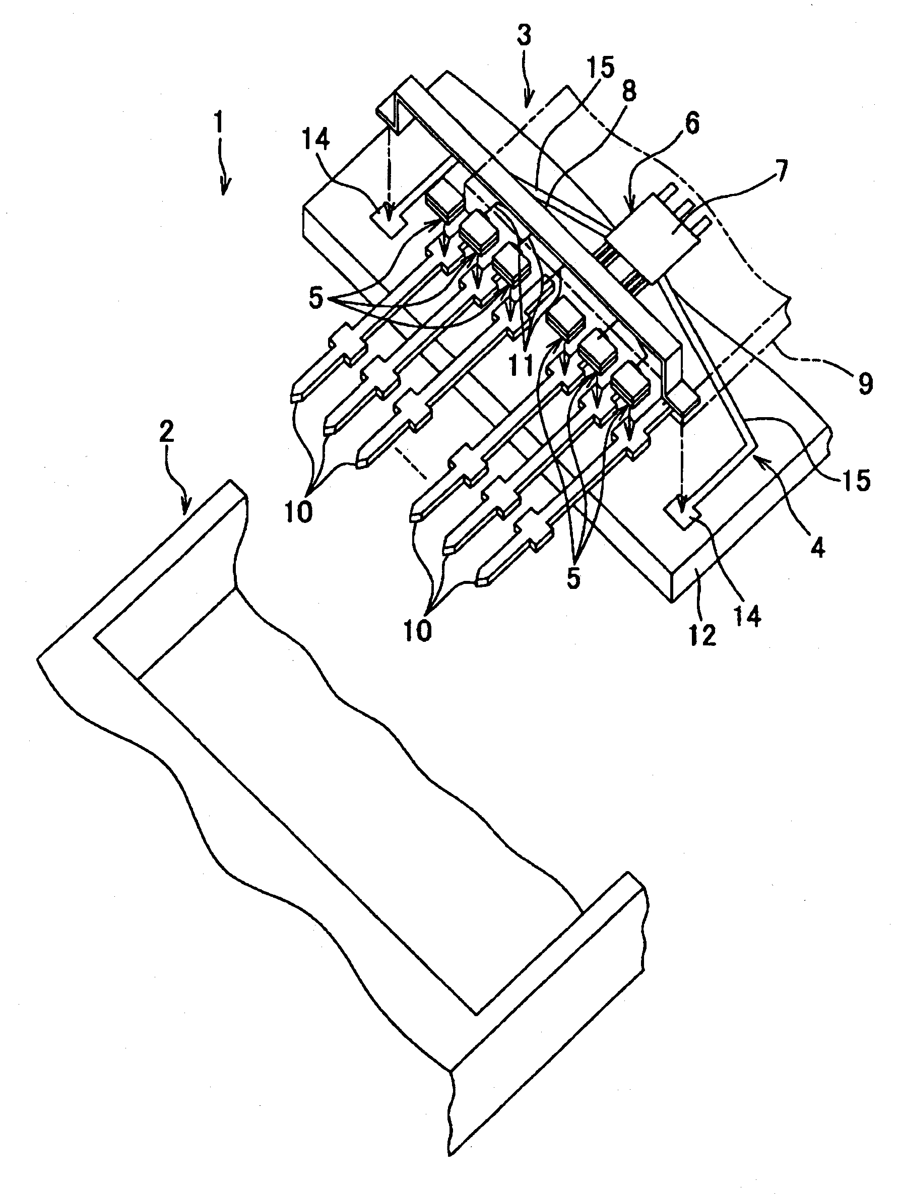
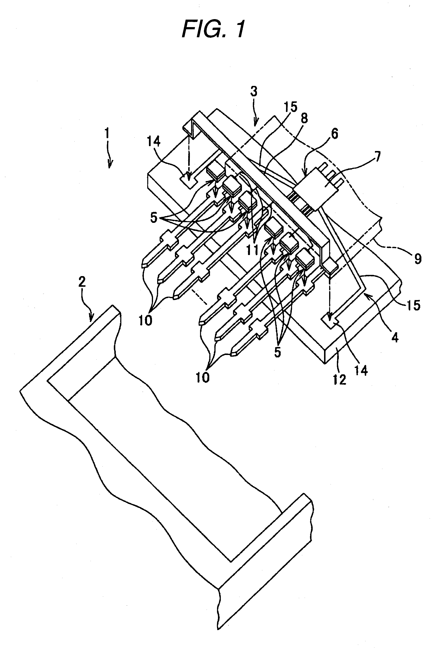
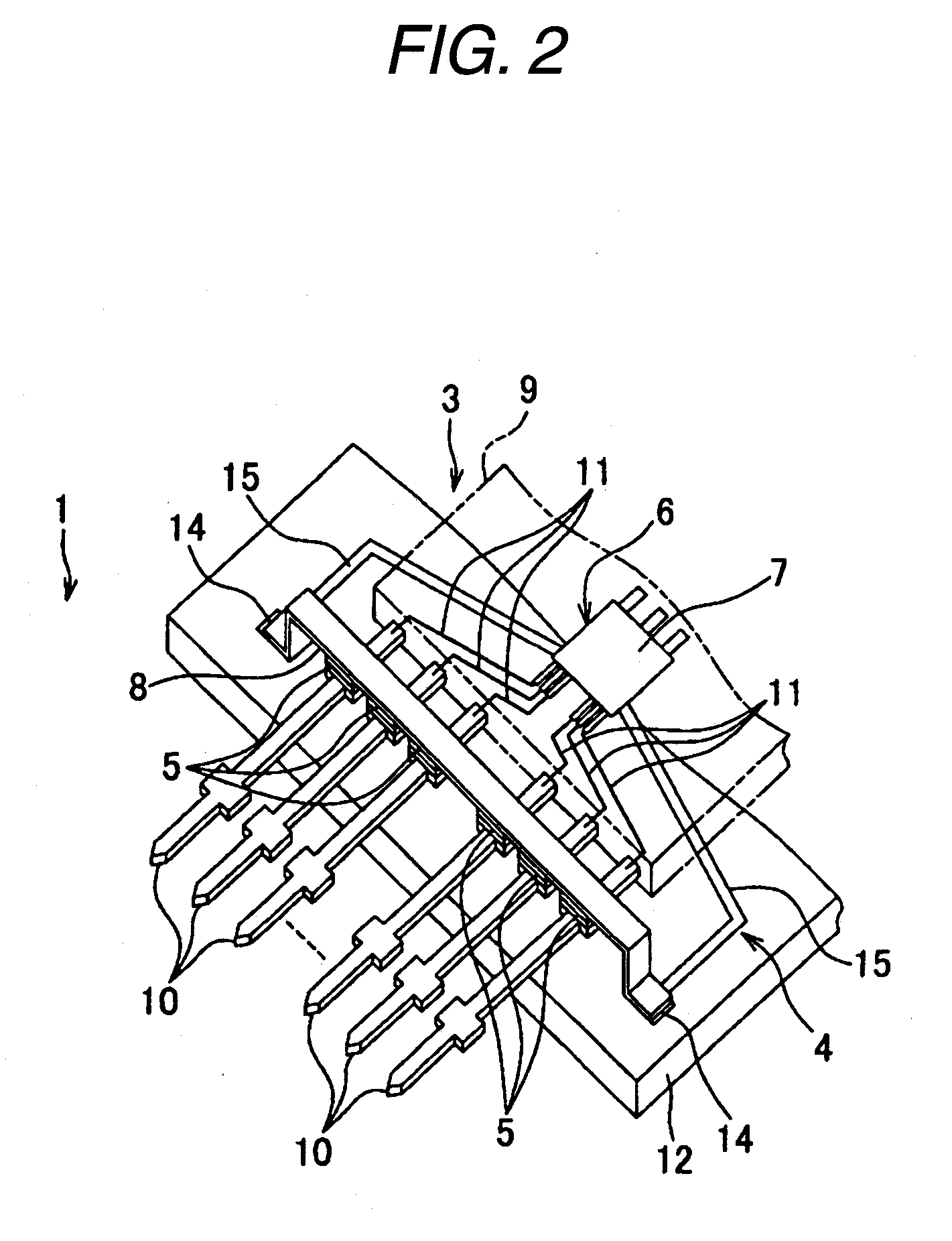
[0024]A connector with a built-in function (hereinafter simply referred to as a connector) as a unit with a built-in control circuit according to the invention will be described referring to FIGS. 1 and 2.

[0025]A connector 1 includes a vehicle communication system mounted on an automobile. The connector 1 is attached to various types of electronic devices (equivalent to external devices) mounted on an automobile and electrically connects these electronic devices to transmit / receive a signal between the electronic devices.

[0026]As shown in FIG. 1, the connector 1 includes an outer housing 2, a control circuit package 3 as a control circuit, a conductive connecting part 4, and capacitors 5 as a plurality of protective elements. The outer housing 2 is composed of an insulating resin and formed into a flat box.

[0027]As shown in FIGS. 1 and 2, the control circuit package 3 includes a lead frame 6, an IC chip 7 as a circuit element, a conductive member 8, and a resin sealant 9. The lead f...

second embodiment

[0042]A connector 1 according to the invention is described referring to FIGS. 5 and 6. The same portion as that in the above embodiment is assigned the same sign and corresponding description is omitted.

[0043]In this embodiment, a conductive member 8 is integrally arranged with a coupling side 15, that is, a conductive connecting part 4. The conductive member 8 is formed integrally with a coupling side 15, that is, the conductive connecting part 4, and forms virtually part of the conductive connecting part 4. In the illustrated example, the conductive connecting part 4 and the conductive member 8 are obtained for example by punching the same sheet metal. The conductive connecting part 4 and the conductive member 8 are supported by the same substrate 12. In this embodiment, capacitors 5 are directly overlaid on and attached to the conductive member 8 without a ground plane 14 being arranged.

[0044]According to this embodiment, in addition to the first embodiment, the conductive membe...


PUM


Abstract

The present invention provides a unit with a built-in control circuit capable of cost reduction. The unit of the present invention is an unit with built-in control circuit comprising a ground line, a control circuit including a plurality of terminals to be connected to an IC-chip, and a plurality of protect elements connected to the terminal and the ground line.

Description

BACKGROUND OF THE INVENTION[0001]The present invention relates to a unit with built-in control circuit housing various types of circuit elements and used for connection of wires and the like.[0002]A vehicle as a mobile object mounts a variety of electronic devices such as an air conditioner, a wiper and a power window. A communication system is used to transmit power or a control signal to the electronic devices. This type of communication system includes a connector with a built-in function as a unit with a built-in control circuit connected to each electronic device.[0003]In the communication system, each connector with a built-in function transmits / receives signals to / from another connector with a built-in function via an external communication line and controls the operation of multiple electronic devices based on the signal transmission / reception. Thus, each connector with a built-in function includes a circuit element composed of a CPU for controlling each connector with a bui...

Claims


Application Information

Patent Timeline
IPC IPC(8): H01R13/648
CPCH01R4/245H01R13/6625H01R43/24H01R31/085H01R13/6658
Inventor ITOU, KENNKANAZAWA, AKIYOSHI
Owner YAZAKI CORP
Learn More