

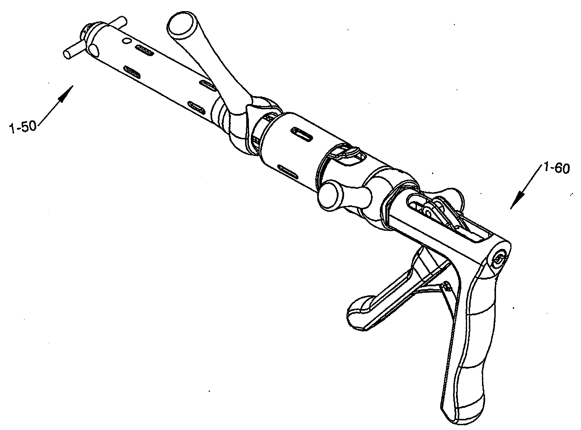
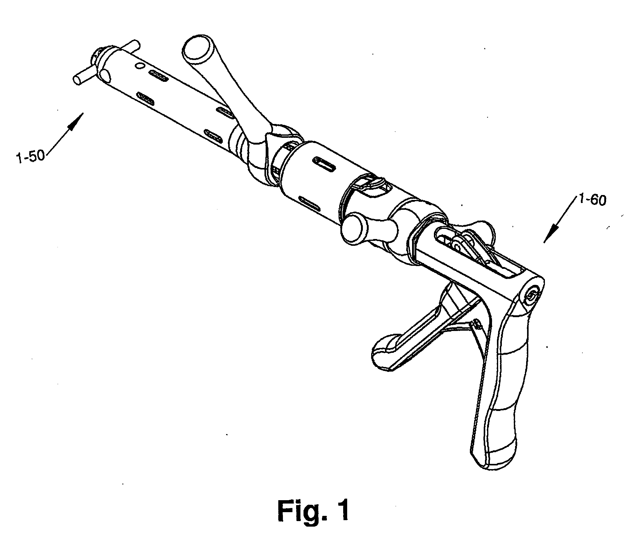
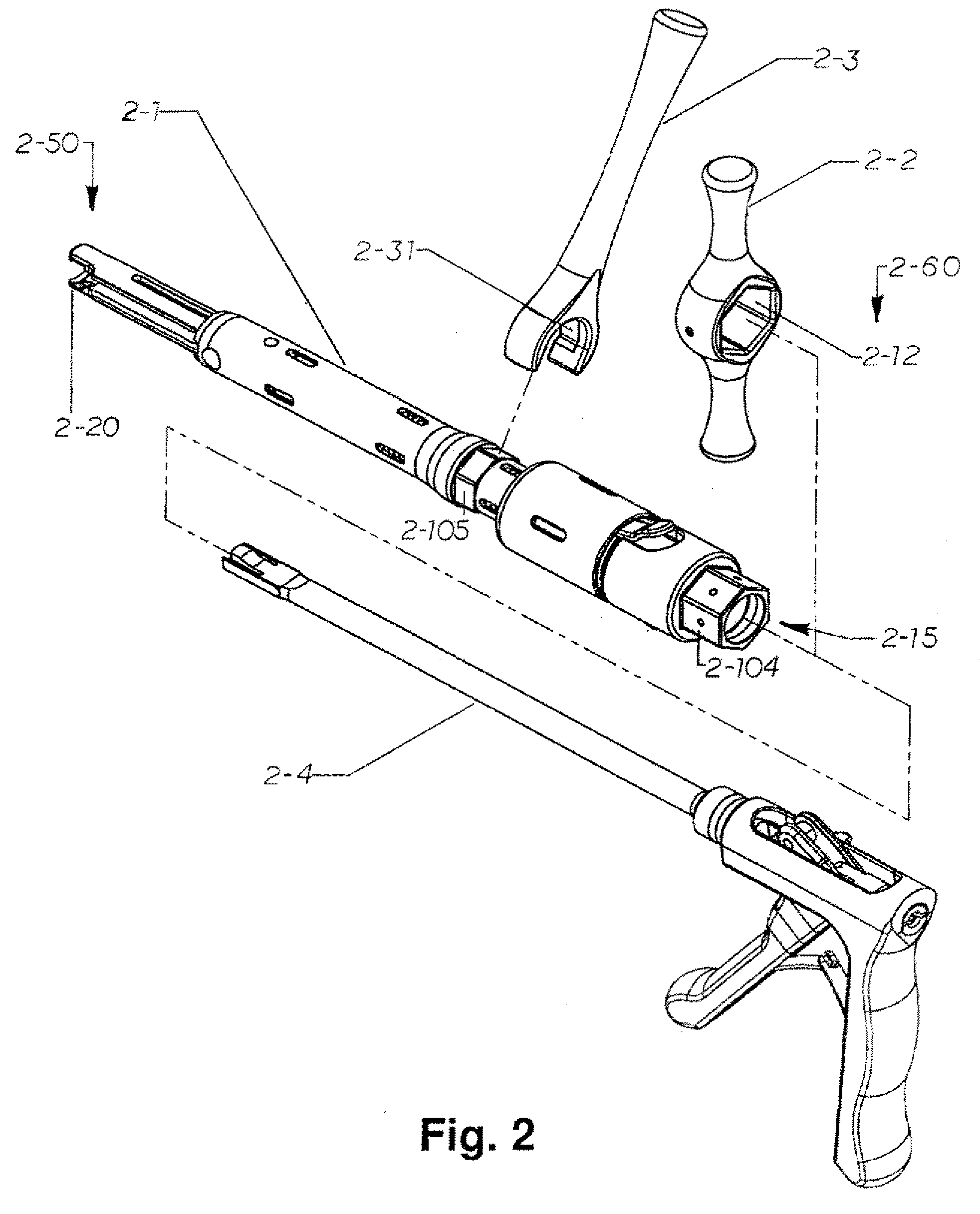
Spinal Rod Reducer and Cap Insertion Apparatus
a technology of reducer and spinal rod, which is applied in the field of spinal rod reducer and cap insertion apparatus, can solve the problems of requiring even additional time and adjustment of the compression member, requiring additional time in the operation, and difficulty for surgeons to reposition or adjust the spinal rod
- Summary
- Abstract
- Description
- Claims
- Application Information
AI Technical Summary
Benefits of technology
Problems solved by technology
Method used
Image

Examples
Embodiment Construction
[0043]The device disclosed herein provides an insertion device for securing spinal fixation systems. In the preferred embodiment, the insertion device is similar to the class of medical instruments generally referred to as spinal rod reducers and cap inserters, but is not limited to that class of devices.
[0044]In addition to the embodiments of the Low Top™ coupling assembly or yoke assembly as described in patent application Ser. No. 11 / 726,868, which is hereby fully incorporated herein, the pedicle screw and yoke assembly can be cannulated, i.e. contain a pathway through the center of the insertion tool and through the entire length of the screw and assembly, so that a guide wire attached to a desired target location and threaded through the screw, assembly, and instrument to direct the system during implantation. A guide wire typically is inserted into a vertebra to achieve an initial accurate location, and the surrounding tissue is then distracted. Once the tissue is distracted, ...
PUM
 Abstract
Description
Claims
Application Information