Metal Pipe and Manufacturing Method Thereof

a technology of metal pipes and manufacturing methods, applied in the field of metal pipes, can solve the problems of energy loss and fluid turbulent friction generation, and achieve the effect of reducing fluid friction and maintaining high-level ridges

Inactive Publication Date: 2009-06-25
SUMITOMO METAL IND LTD
View PDF4 Cites 7 Cited by
  • Summary
  • Abstract
  • Description
  • Claims
  • Application Information

AI Technical Summary

Benefits of technology

[0033]By the method of manufacturing a metal pipe according to the invention, a main surface of a metal plate is ground so that a plurality of ridges having a plurality of different heights can easily be formed at the main surface of the metal plate. Therefore, a metal pipe provided with a plurality of ridges having a plurality of different heights at its inner circumferential surface can readily be produced. The welded pipe itself is provided with the ridges rather than forming ridges at a material (such as a sheet) different from the welded pipe. Therefore, the durability of the r...

Problems solved by technology

The breaking down of the vortex structure and the winding of the strea...

Method used


Image

  • Metal Pipe and Manufacturing Method Thereof
  • Metal Pipe and Manufacturing Method Thereof
  • Metal Pipe and Manufacturing Method Thereof

Examples


example 1

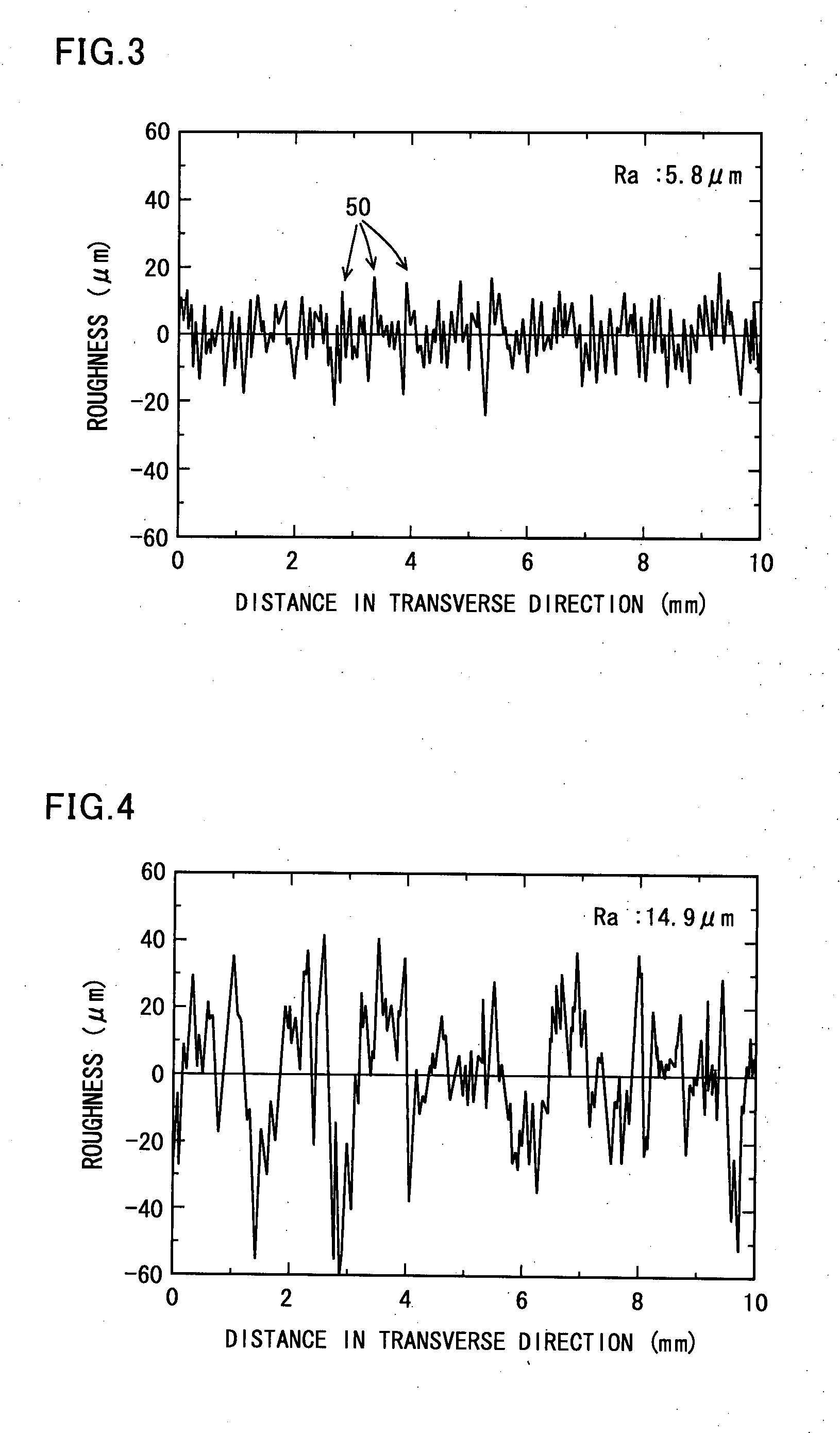
[0088]A surface provided with a plurality of ridges identical in shape, height and interval (i.e., a plurality of riblets) and a surface provided with a plurality of ridges having a plurality of different heights were examined about how much fluid friction was reduced at the surfaces.

[0089]Two pieces of each of the metal plates having surface roughness in Table 2 were prepared.

TABLE 2arithmeticin-meantestridgeheighttervalroughnessNo.kind(μm)(μm)Ra (μm)noteinventive1irregular— 5.8—material2irregular—14.9—comparative3riblet293 598——material4riblet82157——5riblet37 75——6irregular— 5.8isotropicsurfaceroughness7irregular—14.9isotropicsurfaceroughness

[0090]Test No. 1 was a metal plate having a plurality of ridges having different heights that extended in the lengthwise direction on its main surface according to the invention, and the shape of the main surface in the transverse direction was as shown in FIG. 3. The arithmetic means roughness was 5.8 μm. Test No. 2 was a metal plate having a...

example 2

[0110]In metal plates having a plurality of ridges having a plurality of different heights and extending in the lengthwise direction at their main surfaces, the relation between the arithmetic means roughness of the surface in the transverse direction and the reduction in the fluid friction was examined.

[0111]Metal plates having the same sizes as Example 1 had their main surfaces ground with belt sanders in the lengthwise direction to produce a plurality of metal plates including a plurality of ridges having a plurality of different heights and extending in the lengthwise directions at their main surfaces. At the time, belt sanders of different abrasive grain numbers were used so that the plurality of metal plates had different arithmetic mean roughness at the main surfaces in the transverse direction. The plurality of thus produced metal plates each had an arithmetic mean roughness in the range from 0.8 μm to 120 μm. The arithmetic mean roughness (Ra) was calculated based on JIS B0...

example 3

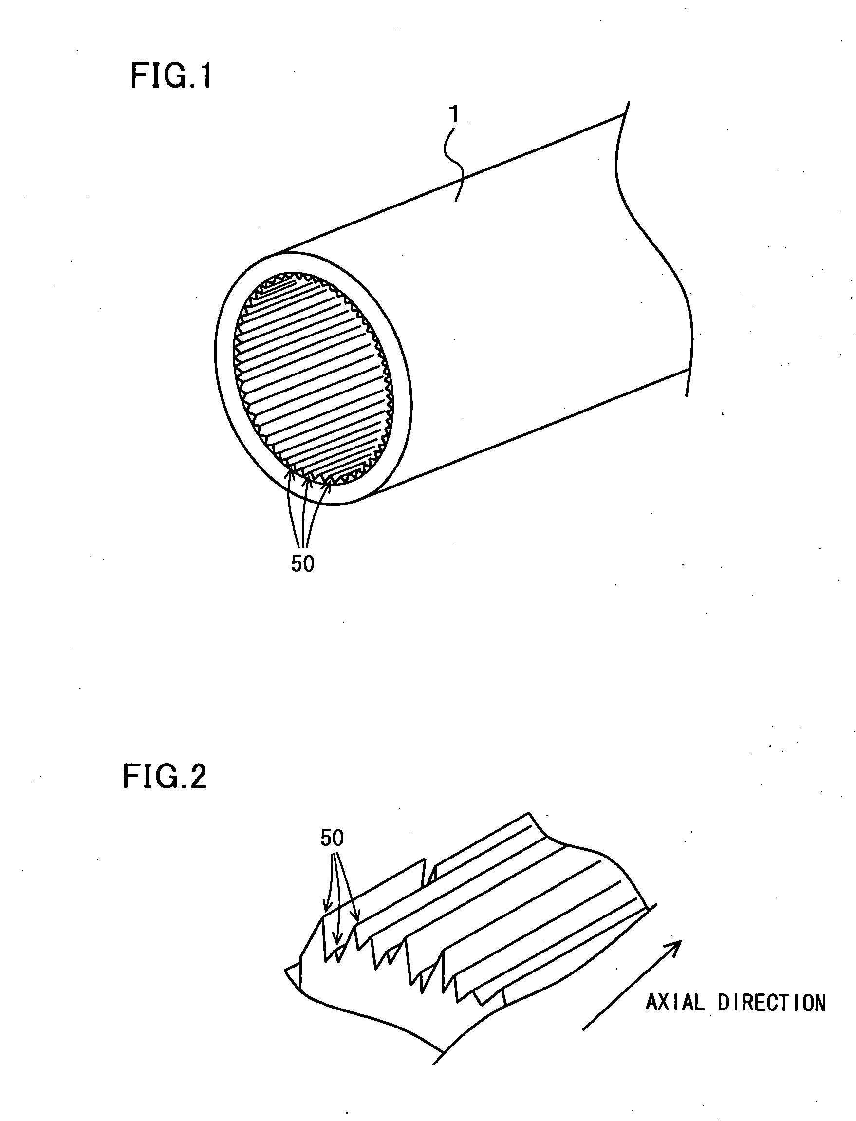
[0119]Assuming that a conventional 13Cr steel pipe and a metal pipe according to the invention including a plurality of ridges having a plurality of different heights and extending in the axial direction at the inner circumferential surface were each applied to a natural gas well, the production of the fluid (natural gas) and wellhead pressure were obtained by simulation.

[0120]Simulation Conditions

[0121]The condition of the gas well was as shown in Table 3. The gas included the components shown in Table 4.

TABLE 3itemconditiondepth3000 m (vertical well)well bottom pressure5310 psig (36.3 MPaG)well bottom temperature230° F. (110° C.)

TABLE 4compositionmol. %CH480.37C2H65.19C3H82.12C4H100.77(CH3)3CH0.45C5H120.31(CH3)2CHCH2CH30.31C(CH3)40.03C6H140.35C7H160.37C8H180.4C9H200.33C10H220.27C6H60.02C6H120.04C6H11CH30.1N23.32CO21.96H2S0.66H2O1.73others0.9

[0122]There were two kinds of metal pipes as shown in Table 5 to be used in the gas well.

TABLE 5simulationarithmetic meanNo.kindroughness (μm)...


PUM

PropertyMeasurementUnit
Mean roughnessaaaaaaaaaa
Fractionaaaaaaaaaa

Abstract

A metal pipe according to the invention has a plurality of ridges that have different heights, extend in the axial direction, and are arranged in the circumferential direction at its inner circumferential surface. If the Reynolds number changes and the streak structure and the scale of a hairpin vortex change, the streak and the hairpin vortex each match any one of the ridges. Therefore, the fluid friction can be reduced in a wide Reynolds number range.

Description

TECHNICAL FIELD[0001]The present invention relates to a metal pipe used to transport a fluid such as water, petroleum, air, and natural gas, and a manufacturing method thereof, and more particularly to a metal pipe for use in an oil well, a gas well, or a geothermal well and a manufacturing method thereof.BACKGROUND ART[0002]When a fluid is passed through a metal pipe, typically a line pipe or an oil country tubular good, there are energy losses caused by fluid friction. If the fluid friction in the line pipe can be reduced, the transporting power can be reduced, and the transporting efficiency can be improved. If the fluid friction in a metal pipe for use in an oil well, a gas well, or a geothermal well can be reduced, the productivity of the fluid such as oil, gas, and steam can be improved, and the use of a metal pipe having a smaller size than the conventional pipes allows the drilling cost to be reduced.[0003]As a measure to reduce such fluid friction in a pipe, a pipe having a...

Claims


Application Information

Patent Timeline
IPC IPC(8): B21B19/04F16L9/00
CPCB21C1/24B21C3/16B21C37/08B21C37/202F16L9/02F15D1/004F15D1/06F16L9/006B21D15/02F28F1/40F24T10/10Y02E10/10
Inventor TAKEISHI, YOSHIAKIAMAYA, HISASHIUEDA, MASAKATSUTAKABE, HIDEKIKIMURA, SHIGEMITSU
Owner SUMITOMO METAL IND LTD
Why Eureka
Try Eureka