Variable valve system for internal combustion engine and its driving mechanism

Active Publication Date: 2009-06-25
HITACHI ASTEMO LTD
View PDF3 Cites 4 Cited by
  • Summary
  • Abstract
  • Description
  • Claims
  • Application Information

AI Technical Summary

Benefits of technology

[0007]Therefore, the driving mechanism is thought to be mounted on a middle position in an axial direction of the control axle. However, since the control axle is formed in a circular shape of cross section, there is a possibility of becoming a linkage structure to the driving mechanism complicated, manufacturing works and assembling works become complex, and a high cost of manufacturing is brought out.
[0008]It is, hence, an object of the present invention to provide a variable valve system for an internal combustion engine which are easy in manufacturing works and in assembling works and require no high cost in its manufacturing.

Problems solved by technology

Consequently, an axial length of the engine becomes accordingly long and an easiness in mounting of the whole engine on the vehicle becomes worsened.
However, since the control axle is formed in a circular shape of cross section, there is a possibility of becoming a linkage structure to the driving mechanism complicated, manufacturing works and assembling works become complex, and a high cost of manufacturing is brought out.

Method used


Image

  • Variable valve system for internal combustion engine and its driving mechanism
  • Variable valve system for internal combustion engine and its driving mechanism
  • Variable valve system for internal combustion engine and its driving mechanism

Examples


Embodiment Construction

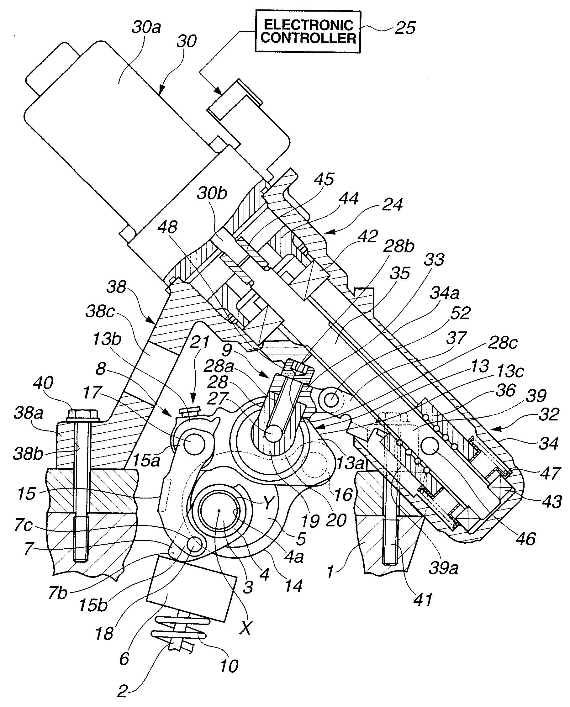
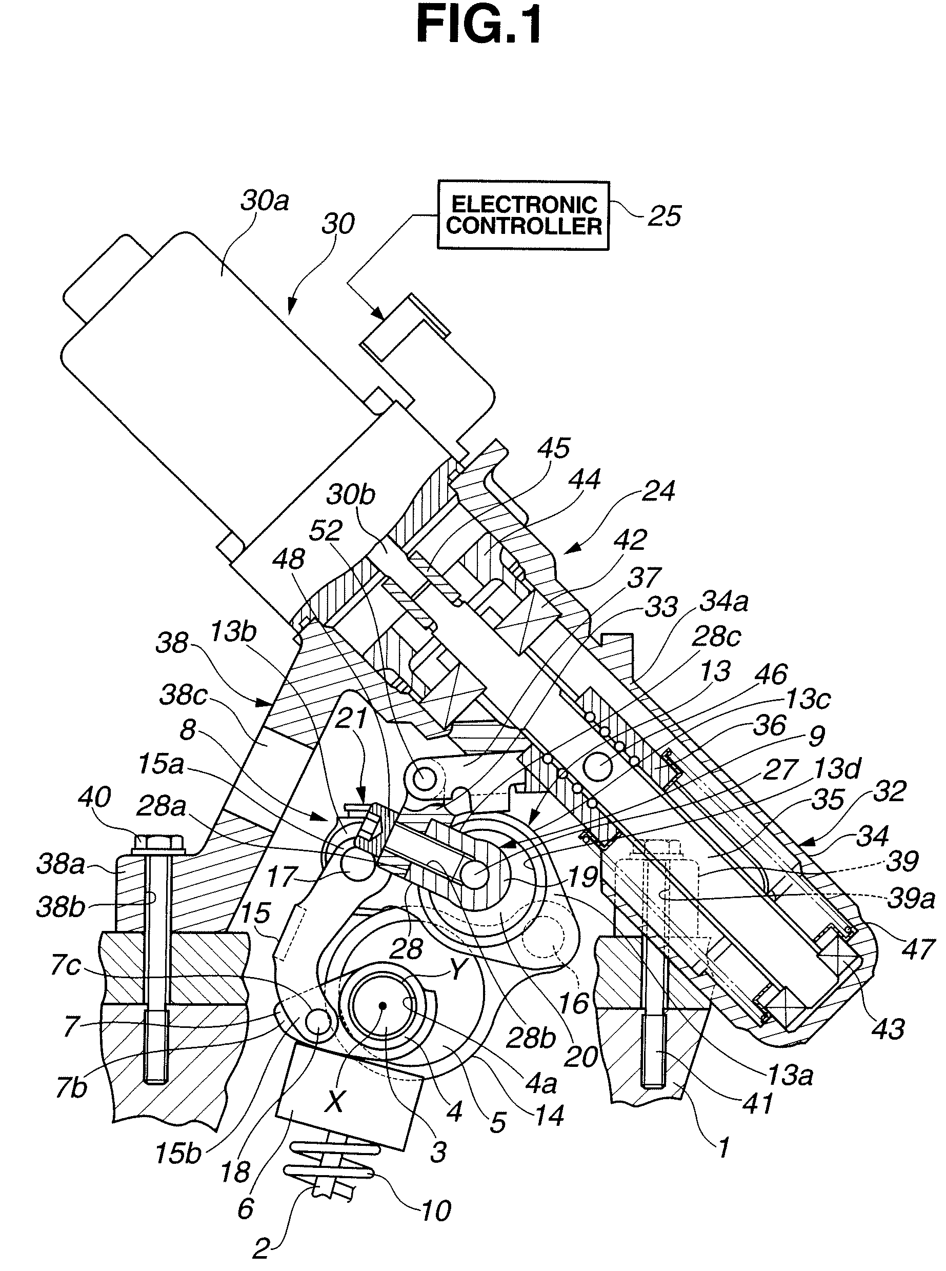
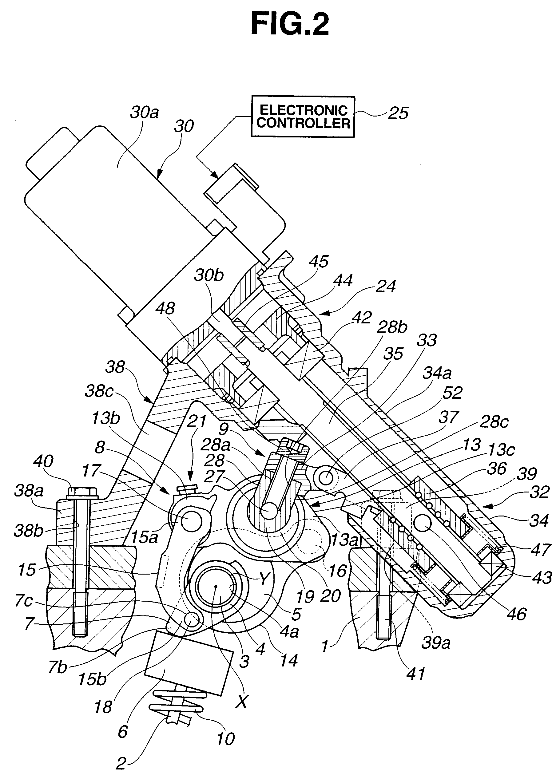
[0024]Reference will, hereinafter, be made to the drawings in order to facilitate a better understanding of the present invention. That is to say, the detailed description of a variable valve system for an internal combustion engine according to the present invention will be made on a basis of the accompanied drawings. In this embodiment, the present invention is applicable to an intake valve side of a multi-cylinder internal combustion engine. The internal combustion engine is equipped with two intake valves for each of the cylinders.

[0025]In details, as shown in FIGS. 1 through 4, the variable valve system includes: a pair of intake valves 2, 2 per cylinder slidably installed on a cylinder head 1 via a valve guide (not shown); a drive axle 3 in an internal hollow configuration and arranged in a forward-or-backward direction of the engine; a camshaft 4 arranged per cylinder and rotatably supported coaxially on an outer peripheral surface of drive axle 3; a drive cam 5 integrally fi...


PUM


Abstract

In a variable valve system for an internal combustion engine and its driving mechanism, the variable valve system comprises: a variable mechanism that revolves a control axle to change an operation characteristic of an engine valve; a projection section projected at an outer peripheral predetermined position in an axial direction of the control axle and on a tip of which a fixture section is formed; a fixture member fixed in a grasped state for the projection member via an engagement member engaged on the fixture section; a driving mechanism configured to provide a rotating force for the control axle via the fixture member; and control means (a control section) for controlling the driving mechanism in accordance with a driving state of the engine.

Description

BACKGROUND OF THE INVENTION[0001](1) Field of the Invention[0002]The present invention relates to a variable valve system which is capable of modifying, for example, a valve lift (quantity) of an intake valve(s) or an exhaust valve(s) for an internal combustion engine and its driving mechanism.[0003](2) Description of Related Art[0004]A Japanese Patent Application Publication No. 2005-273508 published on Oct. 6, 2005 exemplifies a previously proposed variable valve system for an internal combustion engine. The previously proposed variable valve system is applied to an intake valve side. A drive cam which is eccentric from an axial center of a drive axle is installed on an outer periphery of the drive axle revolving in synchronization with a rotation of a crankshaft. In addition, a rotating force of the drive cam is transmitted via a transmission mechanism in a multi-node link configuration and a swing cam is provided whose cam surface is slidably contacted on an upper surface of a v...

Claims


Application Information

Patent Timeline
IPC IPC(8): F01L1/34
CPCF01L1/022F01L1/143F01L13/0026F01L13/0063F01L2001/0475F01L2001/0476F01L1/10F01L2103/00F01L2810/02F01L2820/032F01L2820/042F01L1/044F01L2013/0073F01L2303/00F01L2013/103F01L2303/01
Inventor YAMADA, YOSHIHIKOMAEYAMA, AKINOBU
Owner HITACHI ASTEMO LTD
Why Eureka
Try Eureka