Erecting a wind powerplant

a technology of wind power and rotor, which is applied in the manufacture of machines/engines, hoisting equipment, and final product manufacturing, etc., can solve the problems of cumbersome and expensive removal, high labor cost, and low design cost, and achieve the effect of reducing the complexity of removing the hoisting means and minimizing design costs

Inactive Publication Date: 2009-06-25
SENVION GMBH
View PDF3 Cites 46 Cited by
  • Summary
  • Abstract
  • Description
  • Claims
  • Application Information

AI Technical Summary

Benefits of technology

[0007]In the light of the above state of the art, the objective of the present invention is to improve, in a simple manner, the assembly, respectively the erection and also the dismantling of a wind powerplant, the design costs being minimized and in particular the complexity of removing the hoisting means shall be reduced.

Problems solved by technology

Also, much labor is required in raising a rotor that was assembled on the ground, as appropriate rotation is required once it is raised in the air.
For example, when assembling a rotor designed for applicant's 5M powerplant, two cranes plus (passive) hoists are used which partly engage the outer rotor vane zone and which, following rotor assembly, must be removed in a cumbersome and expensive manner.

Method used


Image

  • Erecting a wind powerplant
  • Erecting a wind powerplant
  • Erecting a wind powerplant

Examples


Embodiment Construction

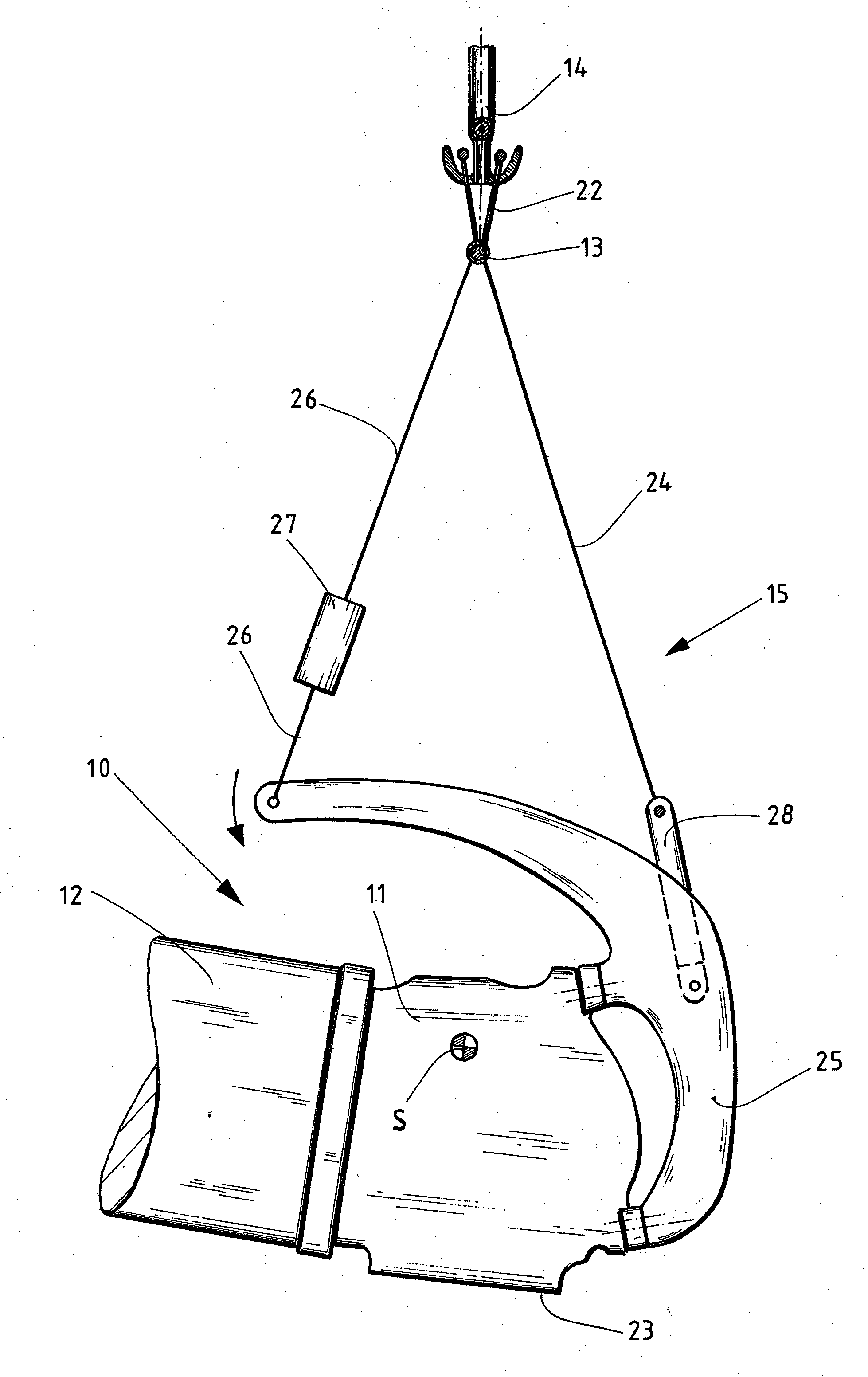
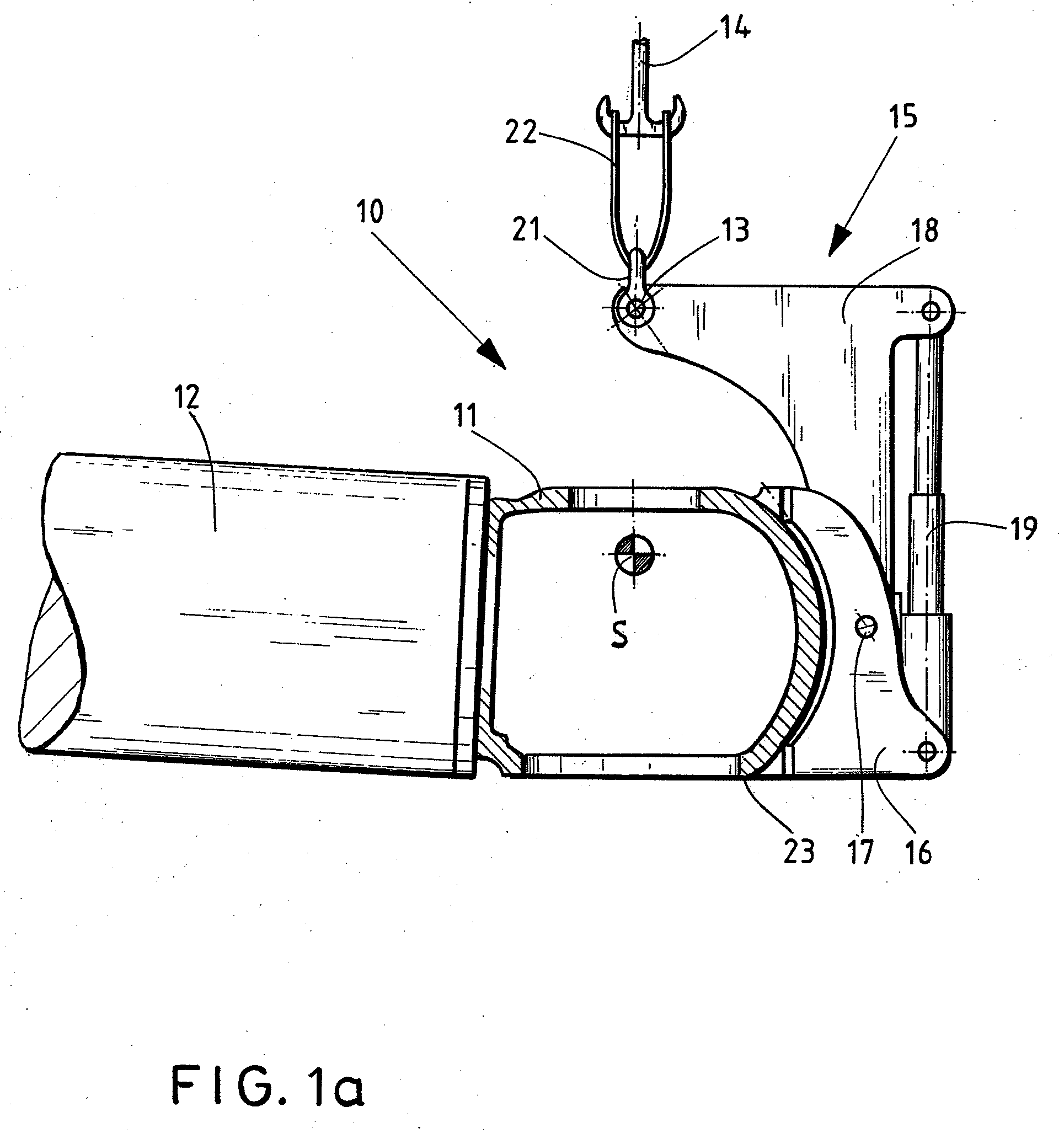
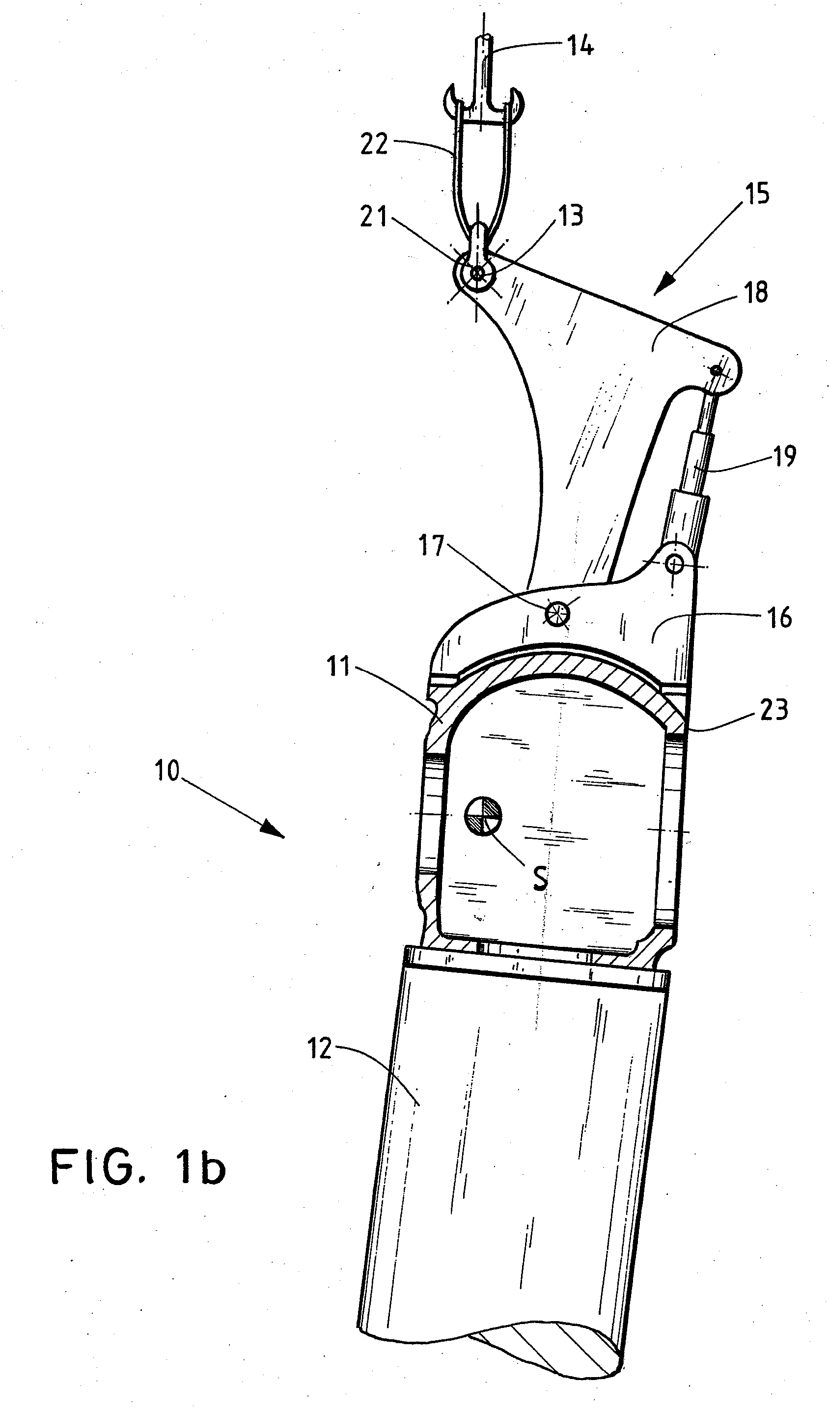
[0055]FIG. 1a is a schematic sideview of a wind powerplant rotor 10 in its raised state, where this rotor 10 comprises a schematic cross-sectionally shown rotor hub 11 and shows a rotor blade 12 mounted on the rotor hub 11.

[0056]In particular, the rotor hub 11 is fitted with several, preferably three equidistant, rotor blades 12 that are joined by flanges to it. Only one rotor blade is shown for clarity.

[0057]The rotor 10 was mounted in its horizontal state on a free, planar surface. Such assembly, for example, may be carried out at a wind powerplant erection site. In case the wind powerplants are erected offshore, the rotors 10 may be finished on land in their horizontal state and then be moved by a floating body to the erection site. At this erection site, the rotors 10 are raised out of their initial horizontal position by means of a crane provided with a boom and with a lifting cable in a manner that said rotor is suspended in a horizontal position from a hook 14 or a grappling ...


PUM


Abstract

A method for handling a wind powerplant's rotor hub (11) or to handle a wind powerplant's rotor (10) using a hoist, in particular for erecting a wind powerplant or for assembling or disassembling a rotor (11) to and from such a powerplant, in particular a hub (11) or a rotor (10) being configured by means of one assembly side to the wind powerplant's tower, the hub (11) or rotor (10) being raised or held by the hoist. In the raised state, the hub (11) is tilted by a tilting mechanism (15) acting on it out of the initial, raised position by a predetermined angle of tilting, or the rotor (10) is tilted by a tilting mechanism (15) acting on the rotor blade roots of the rotor (10) through a predetermined angle of tilting. A mechanism (15) to handle a wind powerplant's rotor hub (11) of a wind powerplant's rotor (10), in particular for assembling or dismantling a rotor to or from its wind powerplant.

Description

BACKGROUND OF THE INVENTION[0001]1. Field of the Invention[0002]The present invention relates to handling a wind powerplant's rotor hub or its rotor, using a hoist, in particular for erecting a wind powerplant or for assembling / dismantling a rotor to / from a wind powerplant. Moreover, the present invention relates also to a mechanism used to handle a wind powerplant's hub, hereafter hub, or its rotor, especially for erecting a wind powerplant or for assembling / disassembling a wind powerplant's rotor to or from it. The present invention again concerns using a tilting mechanism when erecting / disassembling a wind powerplant.[0003]2. Description of Related Art[0004]A large number of steps must be accomplished to erect a wind powerplant. Once its erection site has been made ready, various components of the wind powerplant are moved to its erection site. For example, several tower segments are assembled to each other to constitute one tower during erection, whereupon a crane deposits a nac...

Claims


Application Information

Patent Timeline
Patent Type & Authority Applications(United States)
IPC IPC(8): B66C13/00
CPCB66C1/108B66C1/62F03D1/001Y02E10/728F05B2230/61Y02E10/721F03D1/0658F03D13/10Y02E10/72Y02P70/50
Inventor TREDE, ALFHEINECKE, OLIVEREUSTERBARKEY, CARSTEN
Owner SENVION GMBH
Why Eureka
Try Eureka