

Centrifugal solution spun nanofiber process
a technology of nanofibers and centrifugal solutions, which is applied in the field of nanofiber and fibrous web formation, can solve the problems of agglomeration of too many atomized droplets into larger entities, and achieve the effect of high throughput process
- Summary
- Abstract
- Description
- Claims
- Application Information
AI Technical Summary
Problems solved by technology
Method used
Image

Examples
example 1
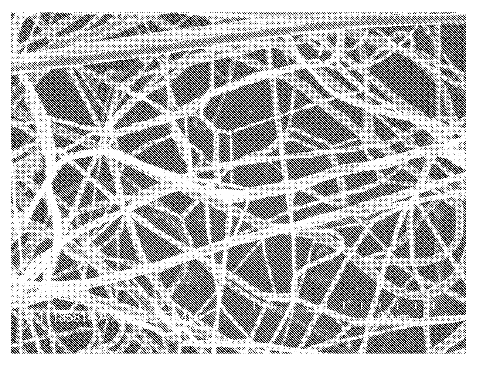
[0034]Continuous nanofibers were made using a lab scale spin unit with a flat disk driven (such as illustrated in FIG. 1) by a high-speed electrical motor. A spinning solution of 8.0 wt % poly(ethylene oxide) with an average molecular weight (Mw) of about 300,000 and 92.0% water by weight was mixed until homogeneous and poured into a syringe pump for delivery to the rotational flat disk with a 3.0 cm diameter through the supply tube with a flow rate of about 2 cc / min. The rotation speed was set to a constant 40,000 rpm. The solution viscosity was 3,150 cP at 25° C. No electrical field was used during this test. Nanofibers were collected on an aluminum foil that was held in tubular shape about 25 cm in diameter surround the spinning disk, and the spinning disk was placed at the center of the tubular collector. There was no shaping fluid applied. An SEM image of the nanofibers can be seen in FIG. 7. The fiber size was measured from images of the nanofibers collected on aluminum foil u...
example 2
[0036]Example 2 was prepared similarly to Comparative Example A, except a 15 cm flat spin disk with reservoir and disk inner edge (such as illustrated in FIG. 6) was used. All test conditions were identical as Comparative Example A. An SEM image of the nanofibers can be seen in FIG. 9. The fiber size was measured from images of the nanofibers collected on aluminum foil using SEM. The fiber diameters were measured from 571 counts of nanofibers and determined to be in the range of 23 nm to 190 nm with a median value of 82 nm. The average fiber diameter was 84 nm with a standard deviation of 27 nm, with a 95% confidence interval.
[0037]The flat spin disk with reservoir used in Example 2 made smaller fiber diameter fibers than the concave spin disk of Comparative Example A.
example 3
[0038]Example 3 was prepared similarly to Example 2, except a 30 cm flat spin disk with reservoir and disk inner edge was used. A spin solution of 12.0% poly(ethylene oxide) with an Mw of about 300,000 and 88.0% water was used. The viscosity of this solution was 34,000 cP at 25° C. In this test, a much higher flow rate was used at 200 cc / min, and the disk rotation speed was 21,000 rpm. There was no shaping air applied. An SEM image of the nanofibers can be seen in FIG. 10. The fiber size was measured from images of the nanofibers collected on aluminum foil using SEM. The fiber diameters were measured from 790 counts of nanofibers and determined to be in the range of 52 nm to 716 nm with a median value of 222 nm. The average fiber diameter was 254 nm with a standard deviation of 122 nm, with a 95% confidence interval.
PUM
| Property | Measurement | Unit |
|---|---|---|
| temperature | aaaaa | aaaaa |
| viscosity | aaaaa | aaaaa |
| viscosity | aaaaa | aaaaa |
Abstract
Description
Claims
Application Information