Battery charging device, three-phase voltage generating circuit, three-phase voltage generation method and delay angle control method

a charging device and battery technology, applied in the direction of electric generator control, transportation and packaging, conversion with intermediate conversion to dc, etc., can solve the problems of large and complex alternating current generators, requiring considerable labor, and consequently high cost, so as to reduce the cost of alternating current generators and simplify the structure. , the effect of reducing the siz

Active Publication Date: 2009-06-25
SHINDENGEN ELECTRIC MFG CO LTD +1
View PDF4 Cites 16 Cited by
  • Summary
  • Abstract
  • Description
  • Claims
  • Application Information

AI Technical Summary

Benefits of technology

[0050]In the present invention, a sub-coil (an auxiliary coil for detecting alternating current output voltage) is provided in any one phase of a three-phase alternating current generator that has U, V, and W phases, and signals that are in synchronization with the alternating current output voltage of the three phases are generated from the alternating current output voltage of the sub-coil of the one phase. As a result, it is possible to achieve a simplification in the structure, a reduction in size, and a reduction in cost of an alternating current generator without having to provide individual magnet position detectors or sub-coils in each phase of the three-phase alternating current generator.
[0051]Furthermore, in the present invention, when performing advance angle / delay angle control by generating signals that are in synchronization with the U, V, and W phases based on the alternating current output voltage of any one phase of a three-phase alternating current generator that has U, V, W phases, the delay angle amount and power generation amount are stored, and when there is a reduction in the power generation amount irrespective of any increase in the delay angle amount, the previous delay angle amount is set as the delay angle limit value. As a result, it is possible to automatically set an optimum delay angle limit value irrespective of the alternating current generator, the type of battery, and the size of the displacement.

Problems solved by technology

In this manner, because it is necessary to provide either a sub-coil or a magnet position detector in each phase of the alternating current generator in order to perform the advance angle / delay angle control, the alternating current generator ends up being large and complex, and is consequently expensive.
In this manner, a large number of tests are carried out in order to determine the optimum delay angle limit value, requiring considerable labor including making tables showing corresponding relationships between the delay angle limit values, the alternating current generators, the batteries, and the displacements determined from the results.
Accordingly, it is necessary to provide a magnet position detector and sub-coil for each phase in order to perform the advance angle / delay angle control such as is described above Thus, the problem of the three-phase alternating current generator being large and complex is not solved.
However, the above described output control device for a synchronous motor of the conventional technology aims to perform battery charging properly while maintaining a superior acceleration performance, and is not intended to solve the problem of excessive labor being required in order to set the optimum delay angle limit value in accordance with the combination of the alternating current generator, the type of battery, and the displacement.

Method used


Image

  • Battery charging device, three-phase voltage generating circuit, three-phase voltage generation method and delay angle control method
  • Battery charging device, three-phase voltage generating circuit, three-phase voltage generation method and delay angle control method
  • Battery charging device, three-phase voltage generating circuit, three-phase voltage generation method and delay angle control method

Examples


first embodiment

(Description of an Example of the Basic Structure of a First Embodiment of the Battery Charging Device of the Present Invention)

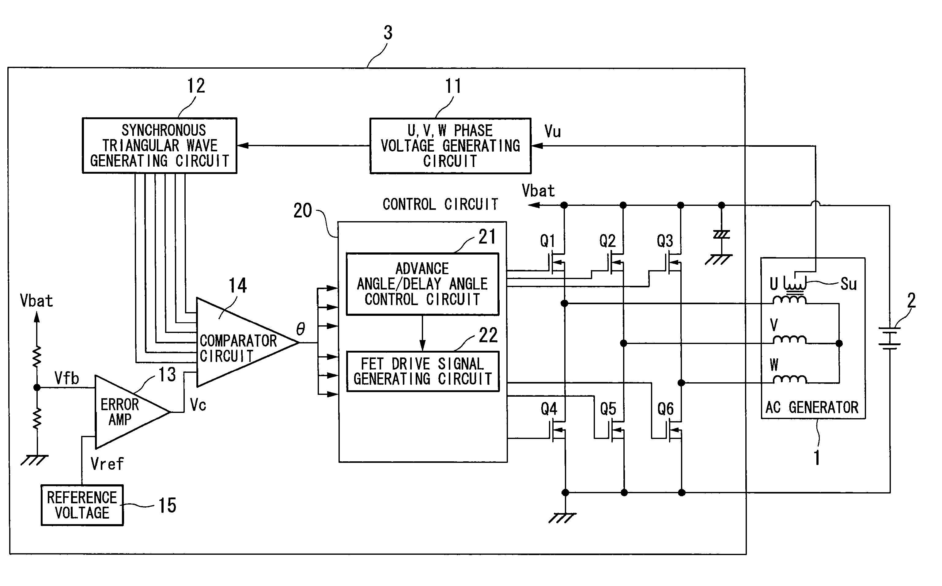
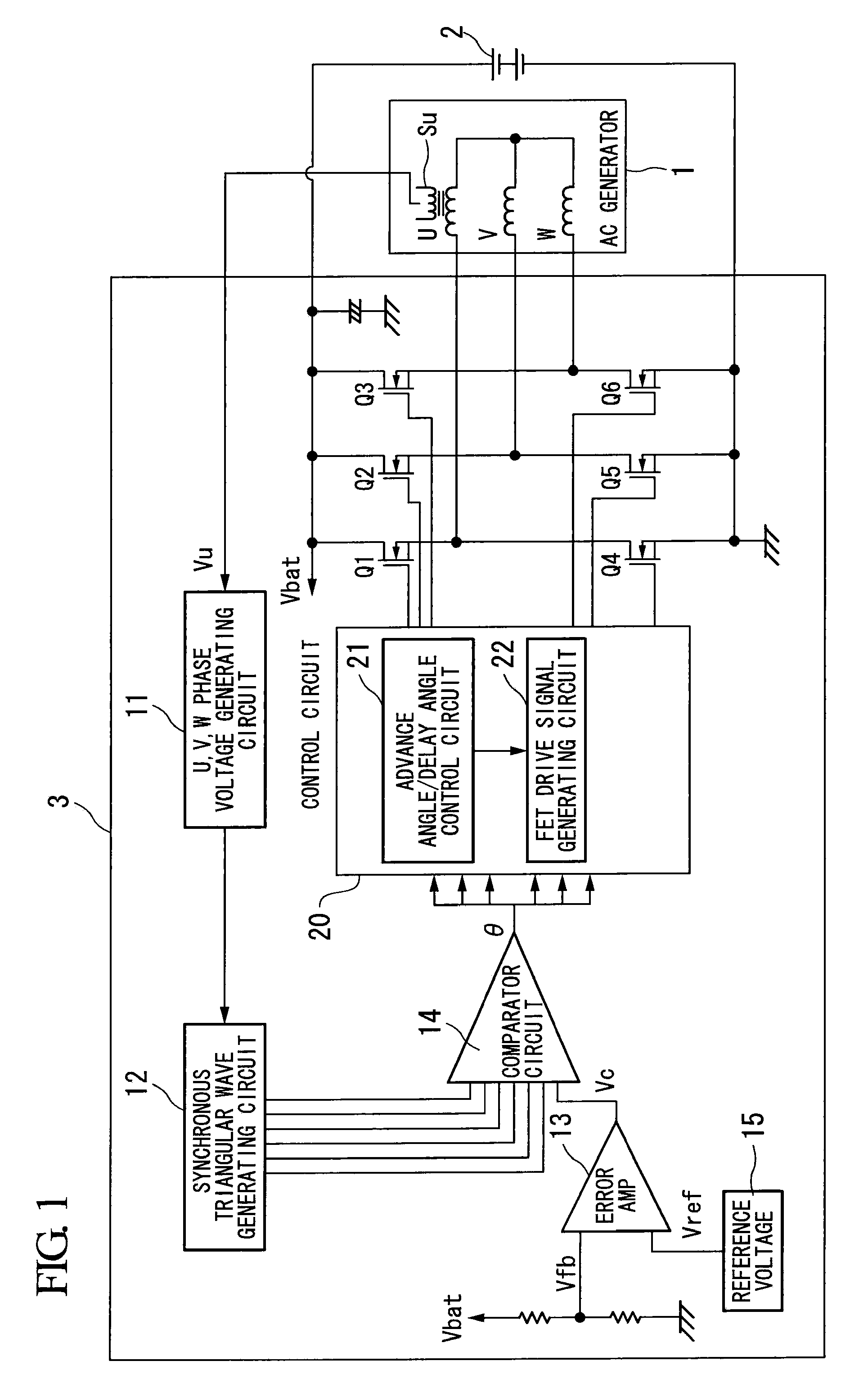
[0089]FIG. 1 is a block diagram showing an example of the basic structure of a battery charging device according to a first embodiment of the present invention, and is an example of a battery charging device 3 that performs full-wave rectification on alternating current output voltage from a permanent magnet type of three-phase alternating current generator (referred to below simply as an ‘alternating current generator’) 1, and charges a battery 2 using this output.

[0090]In this battery charging device 3, a full-wave rectification circuit that rectifies three-phase alternating current output from the alternating current generator 1 has a three-phase bridge configuration of N-channel type power MOSFET switching elements Q1 to Q6. The battery charging device 3 controls the battery charge state (or discharge state) by performing delay angle control or advance ...

second embodiment

(Description of an Example of the Basic Structure of a Second Embodiment of the Battery Charging Device of the Present Invention)

[0158]In the first embodiment, an example is described in which a sub-coil (an auxiliary coil for detecting alternating current output voltage) is provided in any one phase of a three-phase alternating current generator, and signals that are in synchronization with the alternating current output voltage of the three phases is generated from the alternating current output voltage of the sub-coil of the one phase. Advance angle / delay angle control is then performed based on these synchronized signals.

[0159]In the second embodiment of the present invention, an example is described in which, in addition to the basic structure of the first embodiment, when delay angle control is performed, the delay angle is controlled such that it does not increase to more than the delay angle amount that causes the maximum amount of power to be generated by the alternating cu...


PUM


Abstract

In the battery charging device of the present invention, a U, V, W phase voltage generating circuit detects a voltage signal of a U phase sub-coil of a three-phase alternating current generator, and generates a signal of a triangular wave that is in synchronization with the U phase. Moreover, a first triangular wave is generated in synchronization with a phase from 0° to 180° of the U phase rectangular wave, and a second triangular wave is generated in synchronization with a phase from 180° to 360° of the U phase. In addition, a V phase rectangular wave is generated in which the level is inverted at a voltage point of two thirds the peak voltage of the first triangular wave, and in which the level is inverted at a voltage point of two thirds the peak voltage of the second triangular wave, and a W phase rectangular wave is generated in which the level is inverted at a voltage point of one third the peak voltage of the first triangular wave, and in which the level is inverted at a voltage point of one third the peak voltage of the second triangular wave.

Description

TECHNICAL FIELD[0001]The present invention relates to a battery charging device that employs a three-phase alternating current generator and is employed in a two-wheeled vehicle. In particular, the present invention relates to a battery charging device, a three-phase voltage generating circuit, a three-phase voltage generation method, and a delay angle control method that, in a battery charging device that performs advance angle / delay angle control, makes it possible to achieve a reduction in both the complexity and size of the structure of a three-phase alternating current generator, and that is able to automatically set a delay angle limit value.[0002]Priority is claimed on Japanese Patent Application No. 2006-95504, filed Mar. 30, 2006, the content of which is incorporated herein by reference.BACKGROUND ART[0003]FIG. 11 is a view illustrating a battery charging device used in a two-wheeled vehicle and the like.[0004]A permanent magnet type (a type in which a rotor is formed by a ...

Claims


Application Information

Patent Timeline
Patent Type & Authority Applications(United States)
IPC IPC(8): H02J7/14
CPCH02J7/163H02P9/04H02J7/1484H02M7/53871H02M7/219
Inventor SUZUKI, HIDENORIARAI, TATSUYAYANAGISAWA, TAKESHIOTA, ATSUO
Owner SHINDENGEN ELECTRIC MFG CO LTD
Why Eureka
Try Eureka