Transmissive liquid crystal display device
a liquid crystal display and liquid crystal display technology, applied in television systems, instruments, color signal processing circuits, etc., can solve the problems of reducing the efficiency of use of light emitted from a backlight, the amount of light absorbed by the color filter cannot be reduced, and the amount of electricity used by the backlight is increased. to achieve the effect of reducing power consumption
- Summary
- Abstract
- Description
- Claims
- Application Information
AI Technical Summary
Benefits of technology
Problems solved by technology
Method used
Image

Examples
embodiment 1
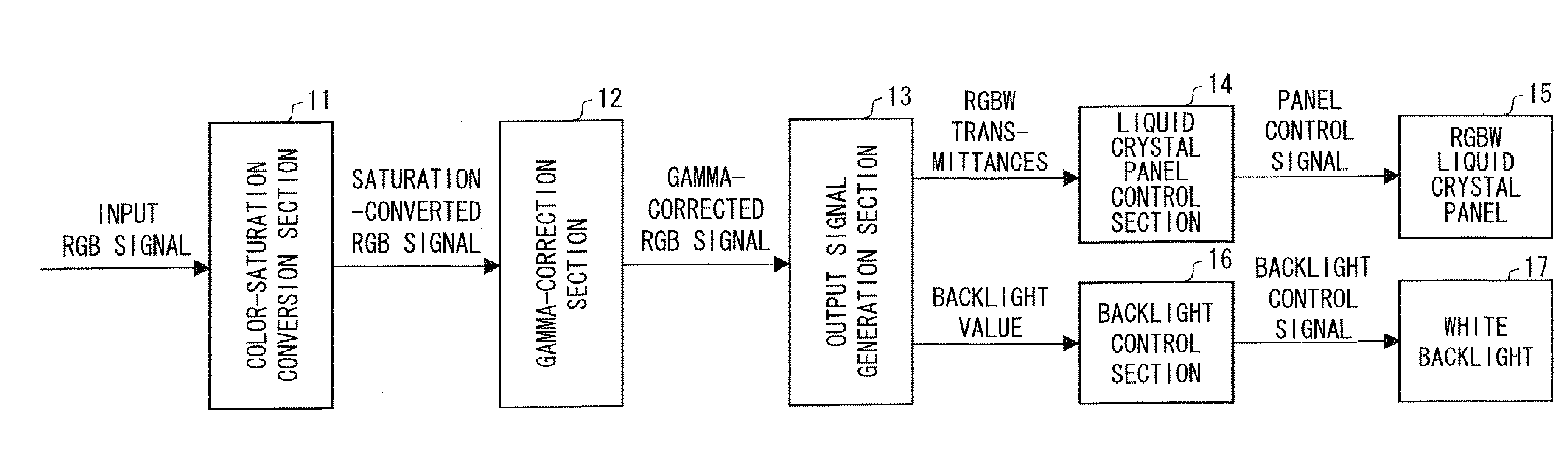
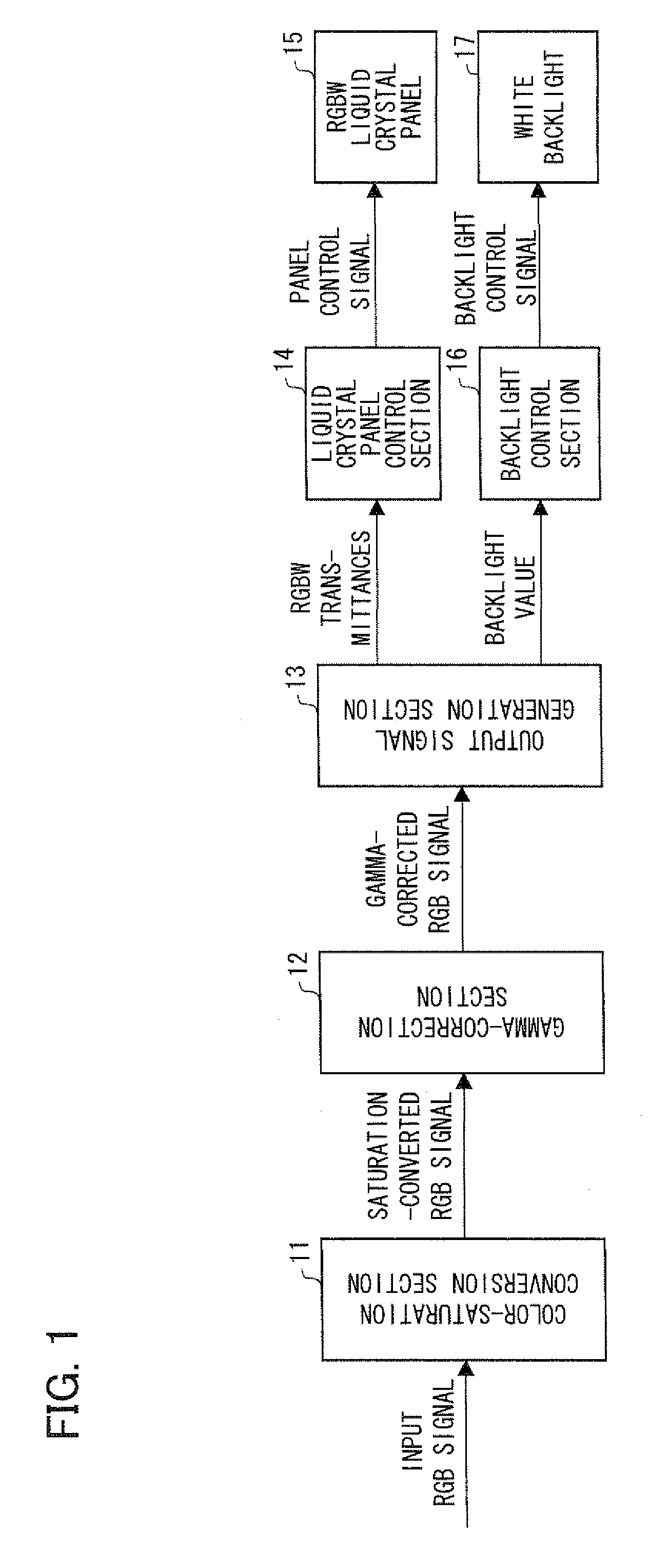
[0106]FIG. 6 shows an arrangement of a color-saturation conversion section 11 of a liquid crystal display device according to Embodiment 1. The color-saturation conversion section 11 includes a backlight upper-limit calculation section 21, a calculation section 22 for calculating the maximum and minimum values of a gamma-corrected RGB signal, a first color-saturation conversion rate calculation section 23, and a saturation-converted RGB signal calculation section 25. Further, FIG. 7 is a flow chart that explains the operation of the color-saturation conversion section 11.
[0107]First, the backlight upper-limit calculation section 21 calculates a backlight upper limit according to Formula (1) below (S11). The color-saturation conversion section 11 performs a color-saturation reduction process only on a pixel low in amount of light that is directly transferred to its W subpixel (i.e., high in color saturation) and high in luminance, but does not perform a color-saturation reduction pro...
embodiment 2
[0215]Embodiment 1 uses Formula (4) to judge for each target pixel whether or not it is necessary to reduce the color saturation. In this case, it is possible to perform a color-saturation conversion (color-saturation reduction) process only on a pixel that satisfies Formula (4), i.e., a pixel whose color saturation needs to be reduced, and to skip a color-saturation conversion process for a pixel that does not satisfy Formula (4), i.e., a pixel whose color saturation does not need to be reduced.
[0216]However, in consideration of realization of the color-saturation conversion section 11 by hardware, the hardware can be better simplified without such a skip process. Embodiment 2 describes a modified example where a color-saturation conversion process is performed on every pixel within an input image. It should be noted that processing sections identical to those of Embodiment 1 are given the same reference numerals as those of Embodiment 1 and will not be described below in detail.
[0...
embodiment 3
[0243]Embodiment 3 is a modified example of Embodiment 1. FIG. 38 schematically shows an arrangement of a liquid crystal display device according to Embodiment 3. That is, the present liquid crystal display device includes a color-saturation conversion and gamma-correction section (color-saturation conversion section) 18 instead of the color saturation conversion section 11 and the gamma-correction section 12 of the liquid crystal display device (see FIG. 1) according to Embodiment 1.
[0244]The color-saturation conversion and gamma-correction section 18 performs a color-saturation conversion process and a gamma-correction process on an input RGB signal (first input RGB signal), and then outputs, to the subsequent output signal generation section 13, a saturation-converted and gamma-corrected RGB signal finished with the processes. It should be noted that the saturation-converted and gamma-corrected RGB signal outputted from the color-saturation conversion and gamma-correction section...
PUM
 Abstract
Description
Claims
Application Information
PatSnap Eureka turns technology decisions into work you can execute. Powered by our Innovation Knowledge Graph, it runs expert workflows across engineering, life sciences, materials and intellectual property. Get your review-ready output in minutes.


