
Methods and system for digitally stabilizing video captured from rolling shutter cameras

a technology of rolling shutter and video camera, applied in the field of digital camera video stabilization, can solve the problems of small number of techniques proposed for use with complementary metal oxide semiconductors (cmos), and the production of unstabilized video cameras is often difficult to predict, and the delay between the two is significan

Active Publication Date: 2009-06-25
APTINA IMAGING CORP
View PDF13 Cites 150 Cited by
  • Summary
  • Abstract
  • Description
  • Claims
  • Application Information

AI Technical Summary

Problems solved by technology

An unstabilized video camera often produces a video image that bounces and jerks according to the movement of the camera user during filming.
Although many video stabilization techniques have been proposed and are currently used with charge-coupled device (CCD) imaging devices, very few techniques have been proposed for use with complementary metal oxide semiconductor (CMOS) imaging devices, such as those widely used in digital cameras and camera phones.
Each pixel row has a same total exposure time, but each row begins its exposure time (and hence also ends its exposure time) at different times. Most significantly, there is a significant delay between the moment the first row is exposed to light and the moment the last or bottom row is exposed to light.
The above-described rolling shutter artifacts are especially noticeable when conventional video stabilization techniques are applied to captured video.
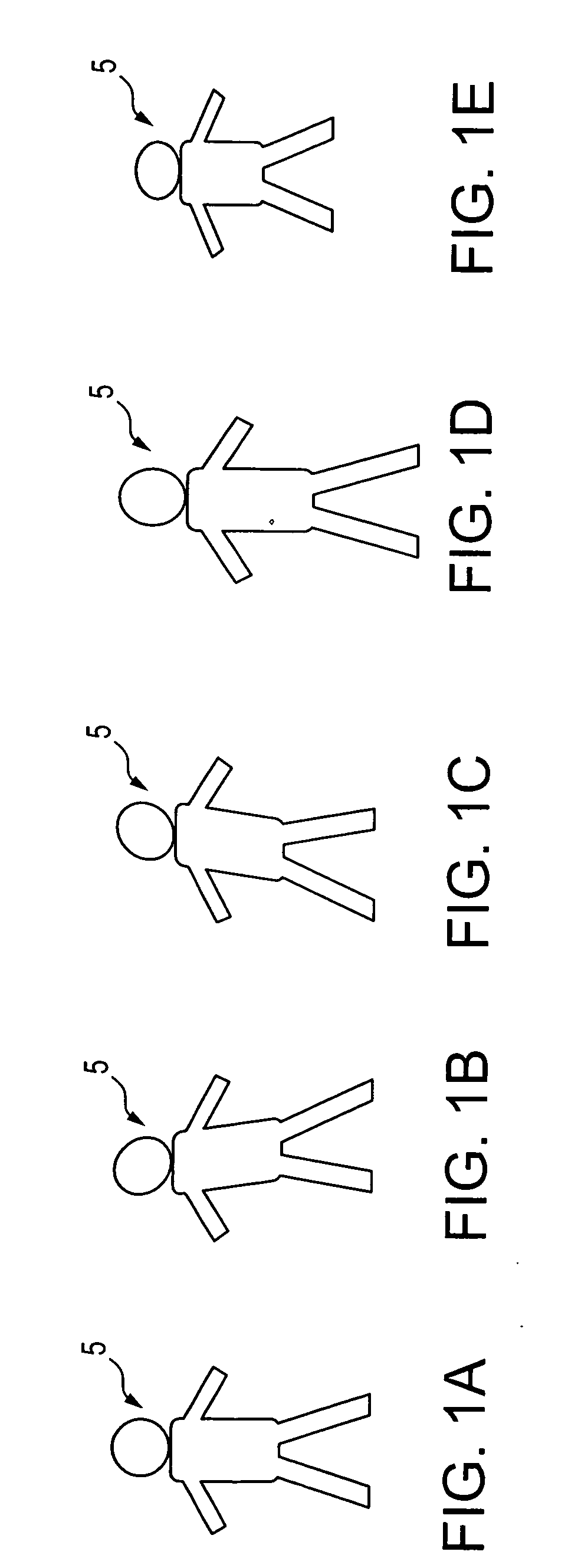
Camera movements from side to side result in the filmed object appearing to wobble instead of standing still, even after video stabilization.
Up and down movements of the camera result in the continuous stretching and shrinking of the filmed object.
Unfortunately, the 3×3 transformation matrix / model makes two critical assumptions that often are not correct.
Thus, although the assumptions used in the translation model are indeed rough approximations of actual camera or object movement, the approximations are not always valid, and thus do not fully compensate for the rolling shutter artifacts in video.

Method used


Image

  • Methods and system for digitally stabilizing video captured from rolling shutter cameras
  • Methods and system for digitally stabilizing video captured from rolling shutter cameras
  • Methods and system for digitally stabilizing video captured from rolling shutter cameras

Examples


Embodiment Construction

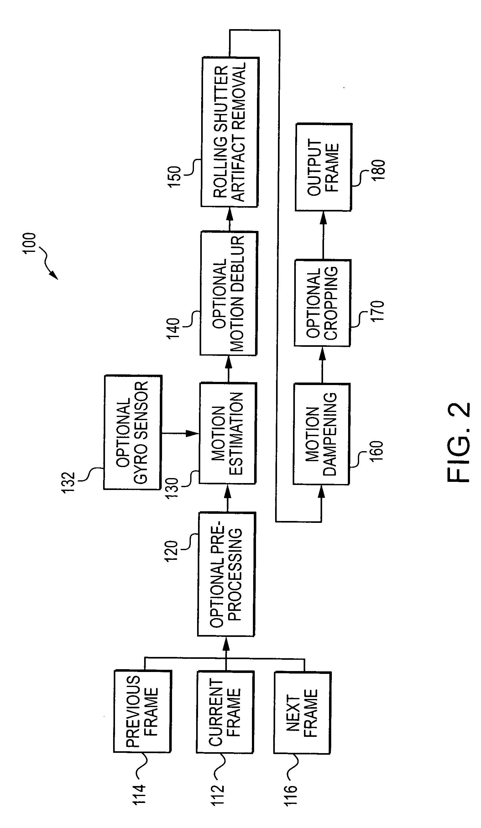
[0020]Video captured using rolling shutter CMOS cameras may be stabilized using the system 100 illustrated in FIG. 2. In FIG. 2, stabilization system 100 includes inputs from a current video frame 112 as well as from a previous video frame 114 and a next frame 116. The current frame is optionally subjected to pre-processing 120, which generally includes noise removal and sharpening of the image. Noise removal and sharpening methods are generally well-known in the art. Examples of noise removal methods include the use of smoothing methods (for example, replacing a pixel's value with an average of the pixel's neighboring pixel values). Examples of sharpening methods include utilizing an unsharp masking filter to increase image contrast near object edges. After the optional pre-processing phase, the current video frame 112 is subjected to a motion estimation analysis 130. During motion estimation, the current video frame 112 is matched with the previous video frame 114 and / or the next ...


PUM


Abstract

An imaging device and methods of stabilizing video captured using a rolling shutter operation. Motion estimation is used to determine a row motion vector for individual rows of a current frame of a pixel array. The row motion vectors are used to map the location of pixels in the current frame to a mapped frame representing a single acquisition time for the current frame.

Description

FIELD OF THE INVENTION[0001]Embodiments of the invention relate to video stabilization in digital cameras, and more specifically to video stabilization in rolling shutter video cameras.BACKGROUND OF THE INVENTION[0002]An unstabilized video camera often produces a video image that bounces and jerks according to the movement of the camera user during filming. In order to remedy this normally undesirable result, digital video stabilization is used as a low-cost alternative to optical stabilization, removing video “jitter” through image post-processing, thus making the video appear as if the camera had been stabilized during use. Although many video stabilization techniques have been proposed and are currently used with charge-coupled device (CCD) imaging devices, very few techniques have been proposed for use with complementary metal oxide semiconductor (CMOS) imaging devices, such as those widely used in digital cameras and camera phones.[0003]Many CMOS imaging devices acquire digital...

Claims


Application Information

Patent Timeline
IPC IPC(8): H04N5/228
CPCG06T7/2026G06T2207/10016G06T2207/20201H04N5/2329H04N5/21H04N5/23248H04N5/3532H04N5/144G06T7/238H04N23/689H04N23/68H04N25/531
Inventor DENG, YININGSILVERSTEIN, D. A.
Owner APTINA IMAGING CORP
Learn More