
Defect inspection system

a technology of inspection system and inspection method, which is applied in the field of inspection system, can solve problems such as the degradation of detection sensitivity, and achieve the effect of preventing the degradation of inspection sensitivity and stable inspection

Inactive Publication Date: 2009-06-25
HITACHI HIGH-TECH CORP
View PDF5 Cites 3 Cited by
  • Summary
  • Abstract
  • Description
  • Claims
  • Application Information

AI Technical Summary

Benefits of technology

[0011]The present invention has been devised in view of the above-mentioned situation. The present invention provides a defect inspection system which, when a plurality of detectors are used, corrects a position at which a sensor is located and makes the focal positions of these detectors coincide with each other, thus preventing the detection sensitivity from degrading.
[0017]The present invention makes it possible to use differences in focal positions of detectors as suitable light-receive conditions by correcting the position of a light-receive system, thus preventing the inspection sensitivity from degrading and accordingly attaining stable inspection.

Problems solved by technology

However, when a wafer height is aligned with an illumination position with respect to an upright detector at the time of adjustment of a detection field of view, the focus of other remaining detectors is not illuminated possibly resulting in degradation of the detection sensitivity.

Method used


Image

  • Defect inspection system
  • Defect inspection system
  • Defect inspection system

Examples


Embodiment Construction

[0029]An embodiment of the present invention will be explained below with reference to the accompanying drawings. While the present embodiment is merely an example for attaining the present invention, it should be noted that the present embodiment does not limit the technical scope of the present invention. In each drawing, elements having the same function are assigned the same symbol.

(1) Configuration of the Defect Inspection System

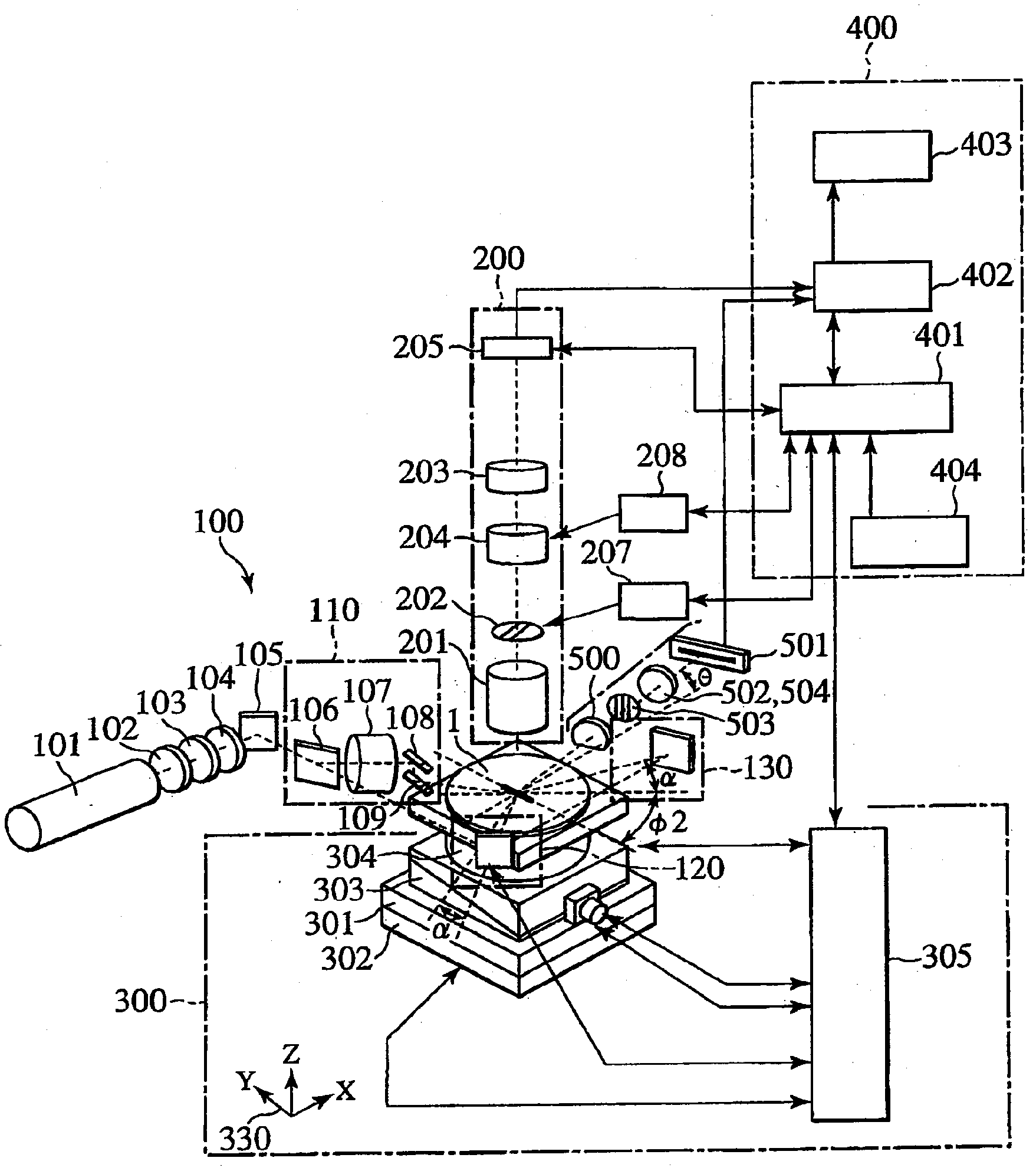
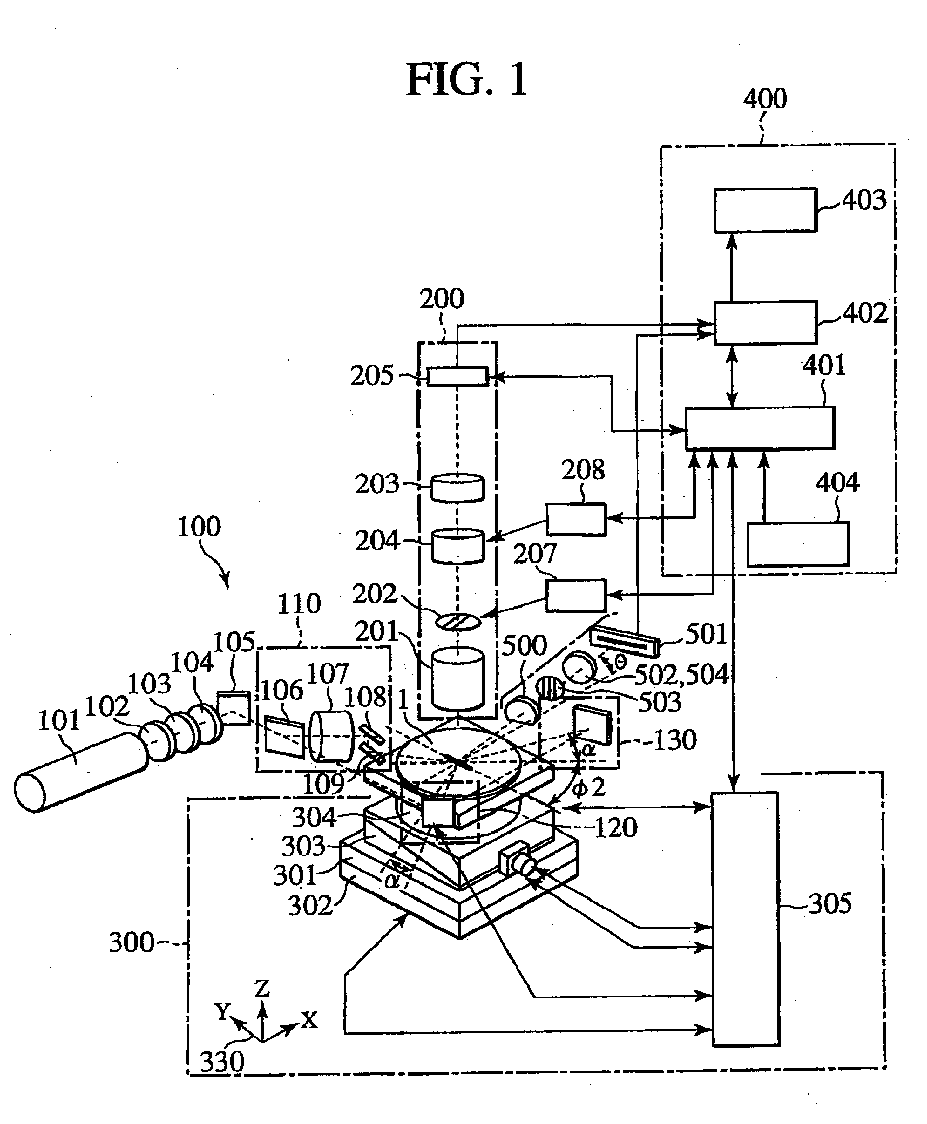
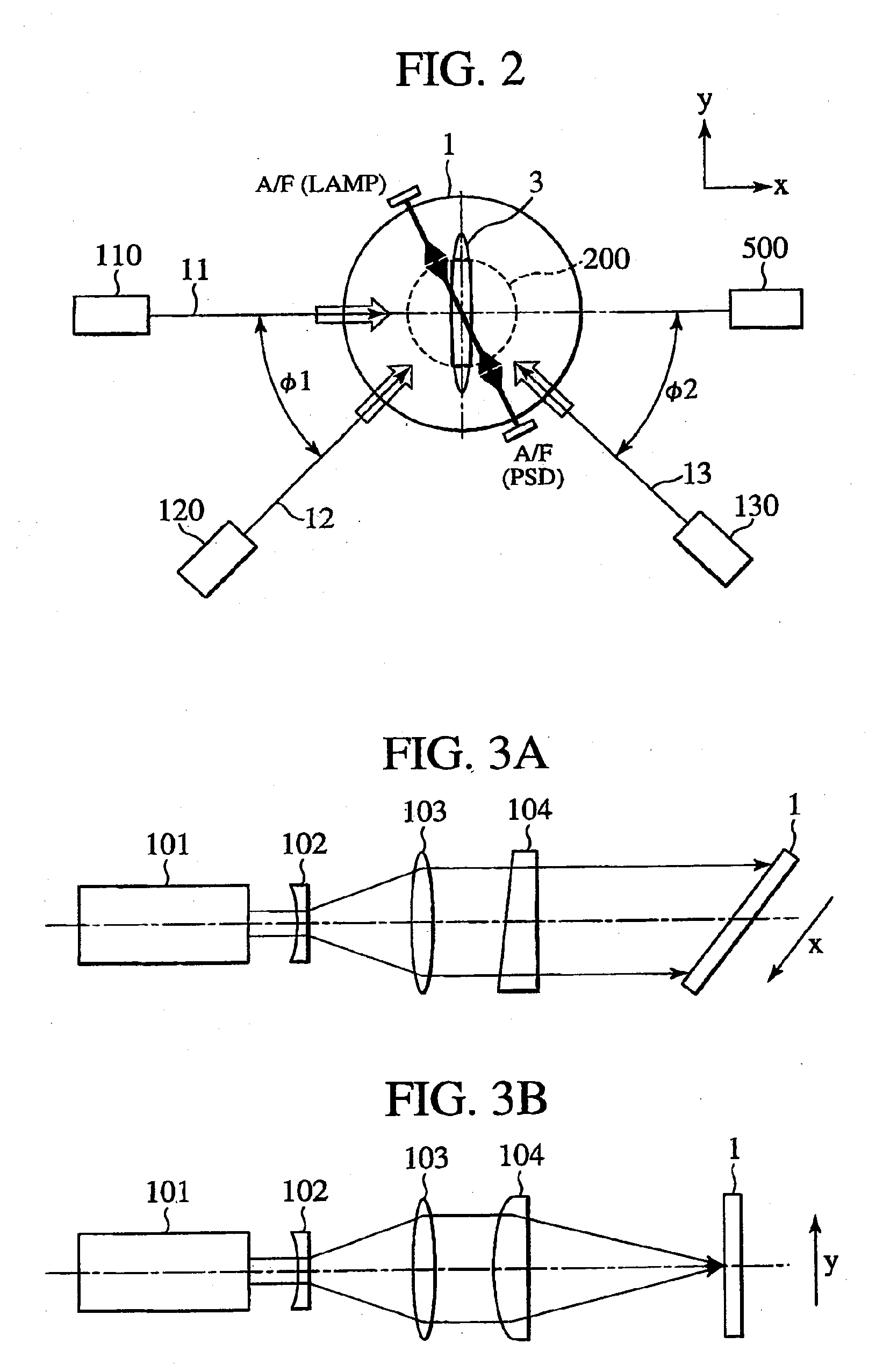
[0030]FIG. 1 shows the schematic configuration of the defect inspection system according to the embodiment of the present invention. Referring to FIG. 1, the defect inspection system includes: a stage system 300 which moves a sample such as a wafer in the x, y, and z directions and around the z axis; an illumination optical system 100 which irradiates the sample with a testing illumination light beam; an upright detector 200 which detects scattered light from the sample; an oblique detector 500 which detects scattered light from the sample; and a contro...


PUM

PropertyMeasurementUnit
defect inspectionaaaaaaaaaa
incident angleaaaaaaaaaa
angleaaaaaaaaaa

Abstract

In a defect inspection system using a plurality of detectors such as an upright detector and an oblique detector, if illumination light and wafer height are adjusted to the detection field of view of one detector, a defocused image is detected by other remaining detectors, resulting in degradation of the detection sensitivity. The present invention solves this problem.When a plurality of detectors such as an upright detector and an oblique detector are used in the defect inspection system, the reduction of the inspection sensitivity can be prevented by correcting the field positions of the other remaining detectors with respect to the field of view of the one detector. Further, the variation in optical axis for each inspection system due to the variation in parts and assembly errors can be reduced.

Description

BACKGROUND OF THE INVENTION[0001]1. Field of the Invention[0002]The present invention relates to a defect inspection system which inspects a defect such as a particle in an object under inspection, and particularly to a defect inspection system suitable for inspection process of a substrate with a pattern, such as a semiconductor wafer, liquid crystal display, and the like.[0003]2. Description of the Related Art[0004]If particles are present on the surface of a substrate in the process of manufacturing a semiconductor device, liquid crystal display, or the like, failures such as short circuit and inferior insulation will take place therein. Causes by which particles are generated include dust that occurs from equipment, the human body, and process gas and other materials.[0005]With the increasing miniaturization in semiconductor process, the minuteness of a defect that will cause failures is also remarkable and accordingly defect detection with higher accuracy is requested.[0006]Rec...

Claims


Application Information

Patent Timeline
Patent Type & Authority Applications(United States)
IPC IPC(8): G01N21/88
CPCG01N21/9501G01N2021/9513G01N21/956
Inventor TANIGUCHI, KOICHIMORITA, YUZO
Owner HITACHI HIGH-TECH CORP
Learn More