Weld viewing

a welding torch and viewing technology, applied in the field of welding viewing, can solve the problems of increasing the difficulty of the job, changing the angle of the welding torch, and repositioning the mirror, so as to extend the reach of the automatic welding system, improve efficiency and reliability

Inactive Publication Date: 2009-06-25
GOUGH YUMA E
View PDF23 Cites 81 Cited by
  • Summary
  • Abstract
  • Description
  • Claims
  • Application Information

AI Technical Summary

Benefits of technology

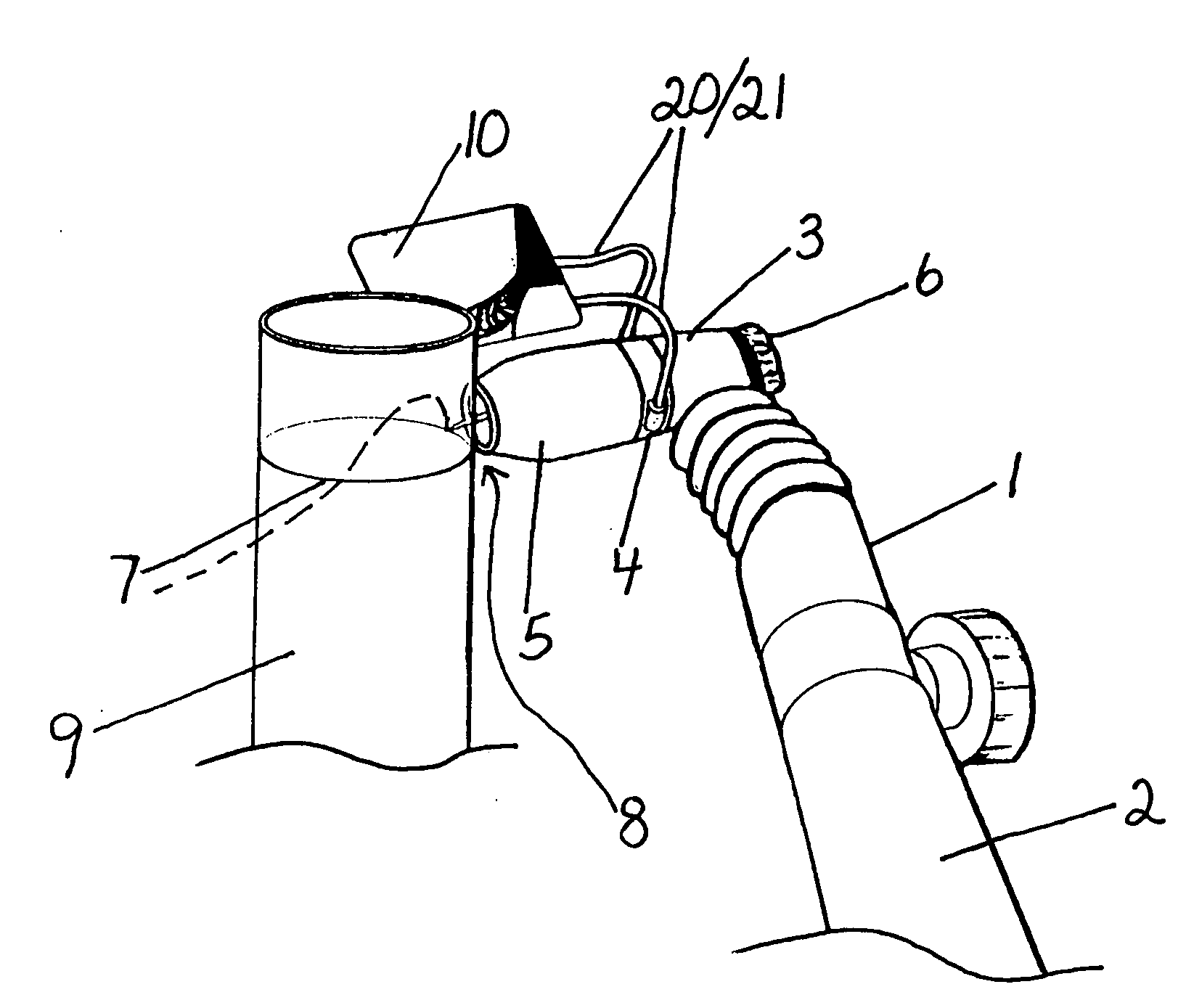
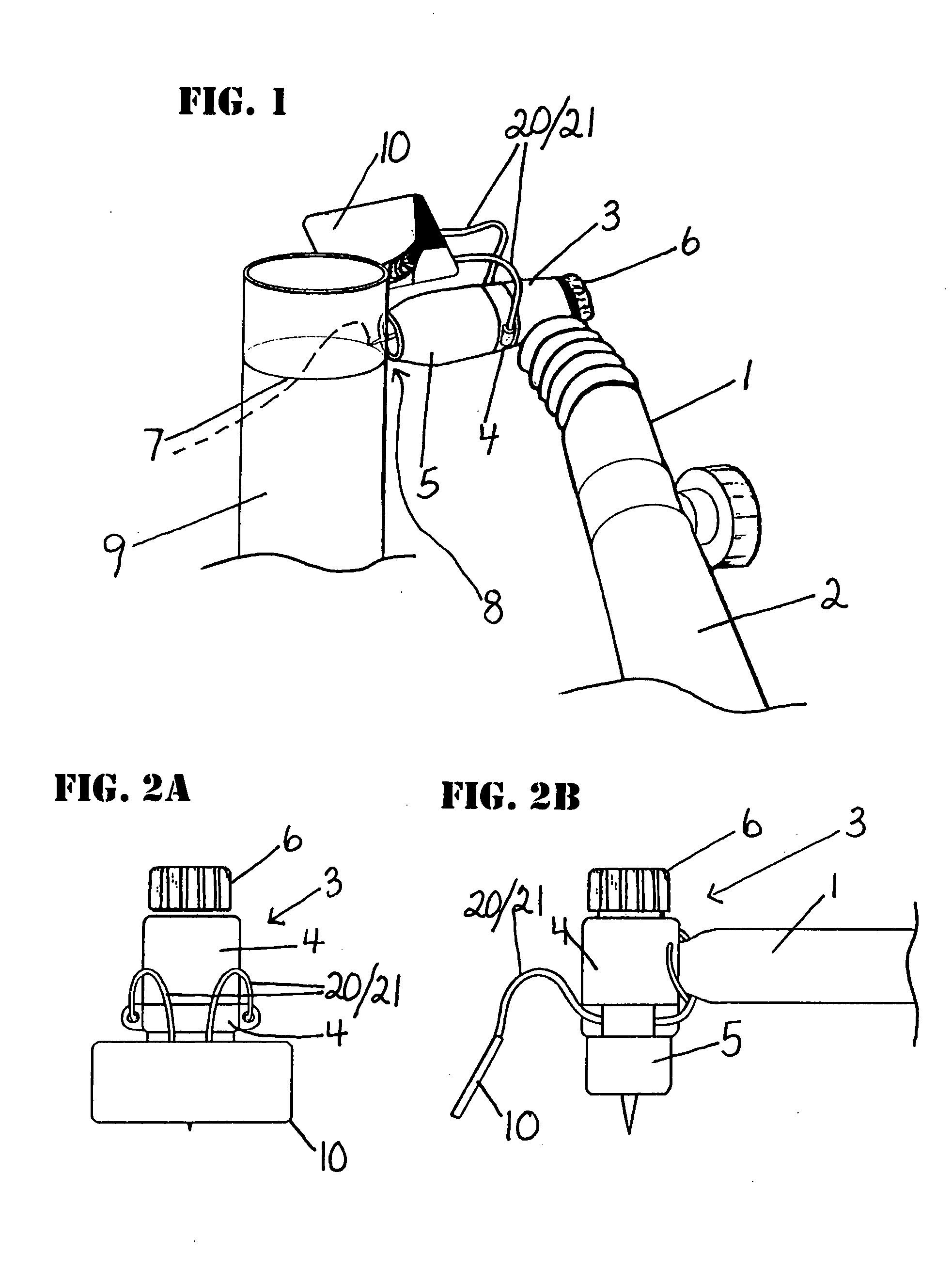
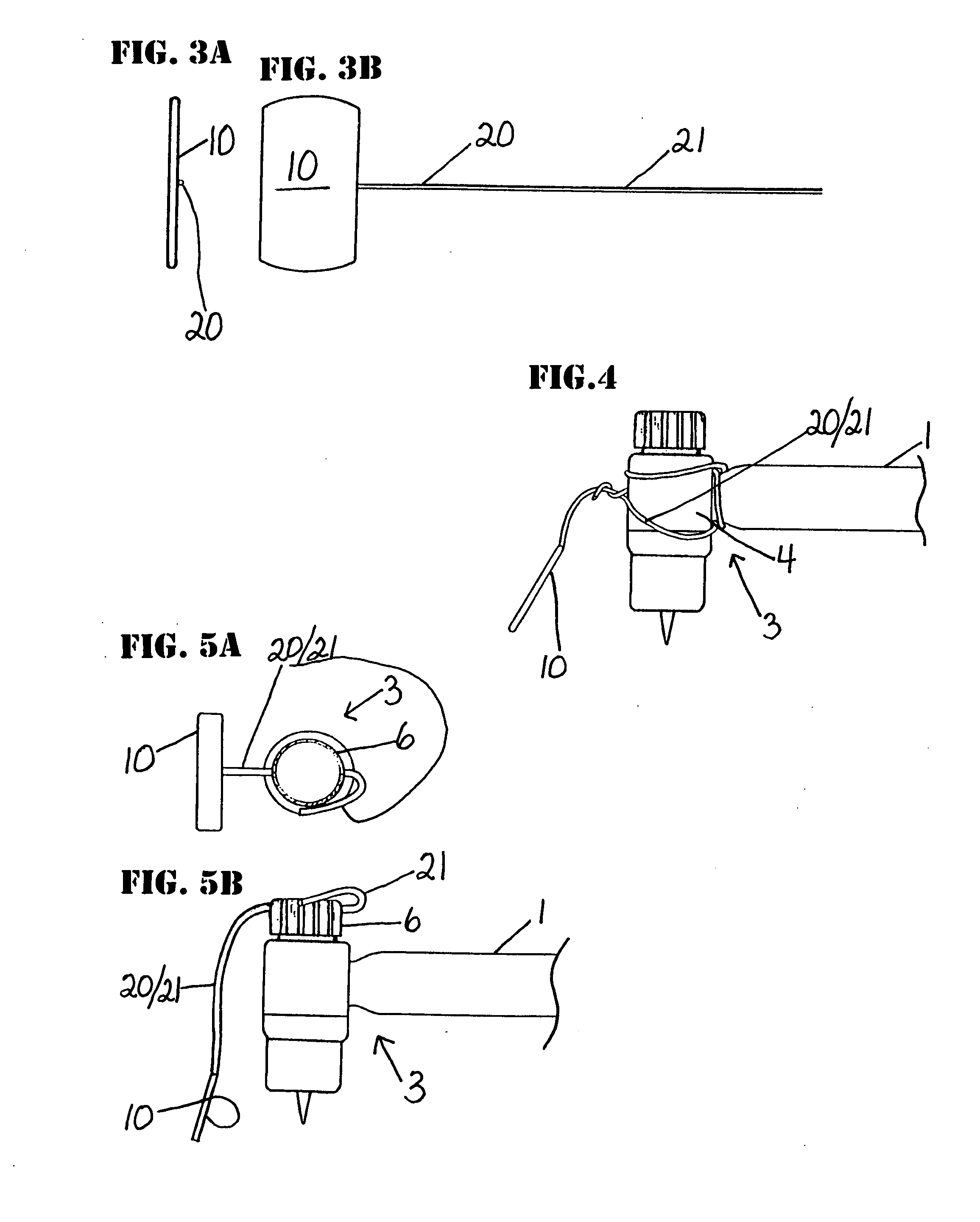
[0013]Significantly, by the invention, the art is advanced in kind. One if not more problems and drawbacks in the art is ameliorated if not overcome, and efficiency and reliability in welds made in obstructed weld sites is notably improved. The adjustable member can be provided simply and efficiently by a flexible member, and it can provide for a mirror of minimal size attached to the head or other portion of a welding torch, and efficiently aid a welder's view of an obscured weld region. It is adaptable to a variety of welding torches, and allows the welder to effectively view the welding operation that is otherwise out of sight when welding in difficult situations. With the mirror attached to the welding torch, the relative angle of the mirror to the welding torch is maintained. This makes viewing the welding operation much easier as the mirror always moves with the welding torch, as opposed to situations in which a mirror is placed in a stationary location adjacent to weld region to be viewed. Furthermore, an economical, compact and transportable solution to remotely viewing a weld region is provided. The mirror, especially with the hole(s) in its viewing surface, can serve as a shield behind which a camera, fiberscope lens, or any image pick-up device can be placed or fitted. Such a mirror can serve not only to shield the sensitive equipment from the intense arc, rays, and heat of the welding operation, but also to reflect arc light back to the weld region. This further illuminates the weld region and increases the amount of light gain for the image pick-up device, and illuminates areas where shadows would otherwise be created from the intense arc light at a low angle of attack to the welding surface. The invention can be compact, rugged, simple, effective, and very economical. It can extend the reach of automatic welding systems. Thus, if an automatic type welding system is used, viewing of the weld region can be facilitated by having the mirror, say, with associated remote viewing equipment, attached to the welding torch or welding head of the automatic or semi-automatic welding machine for direct viewing by the operator. Also, inspections in harsh environments are improved. The instant invention provides alternative(s) to the art.

Problems solved by technology

A problem not infrequently facing a welder is that of an obscured weld site, i.e., an area where a weld is to be made in which some or even none of the area can be seen from the welder's position.
A drawback to this is that it requires the mirror to be placed far enough back from the site of the weld to allow room for the welding torch and filler wire to be passed and operated without hindrance.
The farther back the mirror is placed, the smaller the image in the mirror appears, which increases difficulty in the job and usually results in repositioning the mirror often.
Another problem with a stationary mirror is that the welding torch angle is always changing in the reflection of the mirror as the welding proceeds.
This makes the operation hard to learn.
Generally, such methods are time-consuming, and may put great if not impossible demands on welders.
The number of man-hours involved in team-welding situations can engender high expense.
Such equipment, however, can be damaged from the intensity of heat and the metal spattering that occur about the weld site, and repeated replacement of the equipment can accelerate costs.
In some situations, such known systems are too cumbersome to use, leaving the job to be done manually in its entirety.

Method used


Image

  • Weld viewing
  • Weld viewing
  • Weld viewing

Examples


example 2

[0100]A set of steel tubes in a boiler was in need of TIG welding. The tubes were vertically oriented in close proximity to each other to form a structure generally referred to as wall tubes. The wall tubes had limited access such that only several inches were available inside between the wall tubes and an obstruction. A usual method of having two welders, one on each side of the tubes in need of welding, was not possible to carry out. Welding, which needed to pass X-ray inspection, was needed all around the tubes.

[0101]Management recommended that the front of each tube be cut out to perform what is known as a window weld. A weld would be made to the inside of each tube, and then the cut out portion would be welded back in place.

[0102]The present inventor, said that that proposal was not necessary or desirable, and that he would make the necessary welds without cutting out the fronts of the tubes. The management was skeptical.

[0103]The inventor insisted that the management leave the...


PUM

PropertyMeasurementUnit
sizeaaaaaaaaaa
lengthaaaaaaaaaa
flexibleaaaaaaaaaa

Abstract

A mirror may have hole(s) in or passing through its viewing surface. A video remote may be associated with the mirror, especially as configured with the hole(s). A gas, typically an inert gas, may be passed about or through the mirror system, for example, through one or more of the hole(s) through the viewing surface. The mirror may be part of a mirror system, which can be combined with a welding torch. Obscured sites may be inspected and / or welded therewith.

Description

[0001]This claims the benefits under 35 USC 119(e) of provisional patent application No. 61 / 009,058 filed on Dec. 21, 2007 A.D. The complete specification of that application, to include its drawings, is incorporated herein by reference.FIELD AND PURVIEW OF THE INVENTION[0002]This concerns a visual aid for welding, for example, a mirror with or without a hole in it and with or without an accompanying video remote, and use of the visual aid in welding or inspecting. The mirror can be fixed about a welding torch. Gas tungsten arc welding (GTAW), also known as tungsten inert gas (TIG) welding, and TIG welding torches and / or plasma arc welding (PAW) and PAW torches can be of special concern.BACKGROUND TO THE INVENTION[0003]A problem not infrequently facing a welder is that of an obscured weld site, i.e., an area where a weld is to be made in which some or even none of the area can be seen from the welder's position. Several known devices and methods attempt to address this.[0004]For exa...

Claims


Application Information

Patent Timeline
Patent Type & Authority Applications(United States)
IPC IPC(8): G02B27/22G02B5/08
CPCB23K9/167B23K10/02B23K9/32B23K9/291
Inventor GOUGH, YUMA E.
Owner GOUGH YUMA E
Why Eureka
Try Eureka