Transreflectors, transreflector systems and displays and methods of making transreflectors

a technology of transflectors and reflectors, applied in the field of transflectors, can solve the problems of less than 50% reflection, less than 50% transmission of light incident on the device, and inability to obtain 100% transmittance of light striking the transreflector from below and 100% reflection of light striking the transreflector from above, so as to increase efficiency and increase efficiency

Inactive Publication Date: 2009-06-25
INNOVATIVE DISPLAY TECH
View PDF34 Cites 48 Cited by
  • Summary
  • Abstract
  • Description
  • Claims
  • Application Information

AI Technical Summary

Benefits of technology

[0018]Likewise, the backlight may have a pattern of individual optical deformities for producing a particular light output distribution from its light emitting surface that have a well defined shape including at least one sloping surface for reflecting or refracting light impinging on the optical deformities out of the light emitting surface. The sloping surface of at least some of these deformities may be oriented to face an optically coupled area of the light input edge across the backlight. Also, at least some of the deformities, which may comprise depressions in or projections on the light emitting portion of the backlight/panel member, may vary in size, shape, depth or height, density and/or orientation across the backlight. Moreover, the deformities may be randomized, staggered, or arranged in a stochastic pattern across the backlight. Further, at least some of the deformities may be arranged in clusters across the backlight, with at least some of the deformities...

Problems solved by technology

Since it is not physically possible to create a transreflective device that has zero light absorption, a beam splitter type transreflector device that attempts to both transmit and reflect the maximum amount of light incident on the device will be limited to less than 50% transmission and less than 50% reflection.
Optical losses in the transreflective device, absorption for example, make it impossible to obtain 100% transmittance of light striking the transreflector from below and 100% reflection of light striking the transreflector from above.
Beam splitter type transreflectors tr...

Method used


Image

  • Transreflectors, transreflector systems and displays and methods of making transreflectors
  • Transreflectors, transreflector systems and displays and methods of making transreflectors
  • Transreflectors, transreflector systems and displays and methods of making transreflectors

Examples


Embodiment Construction

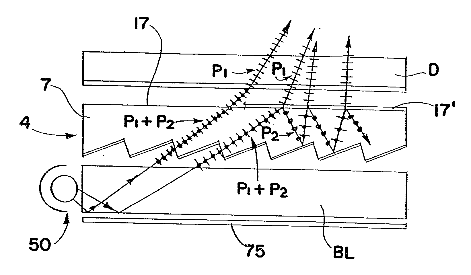
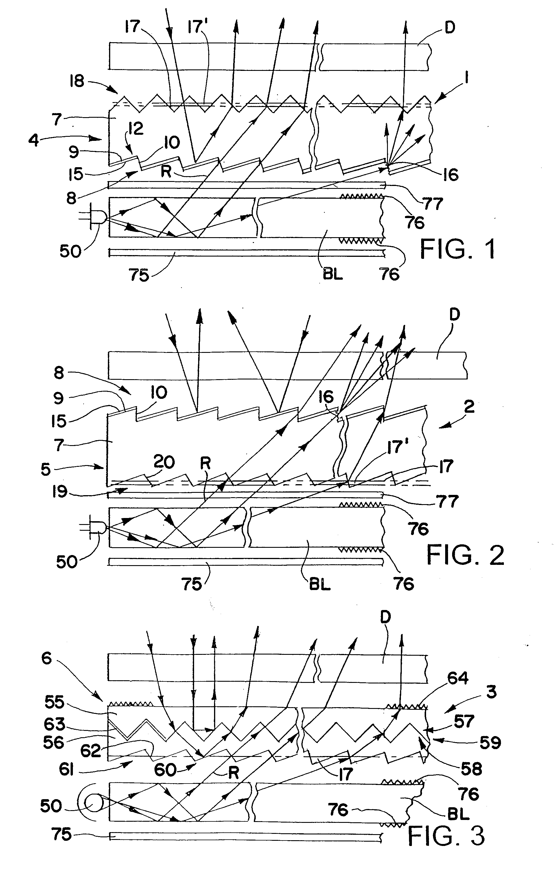
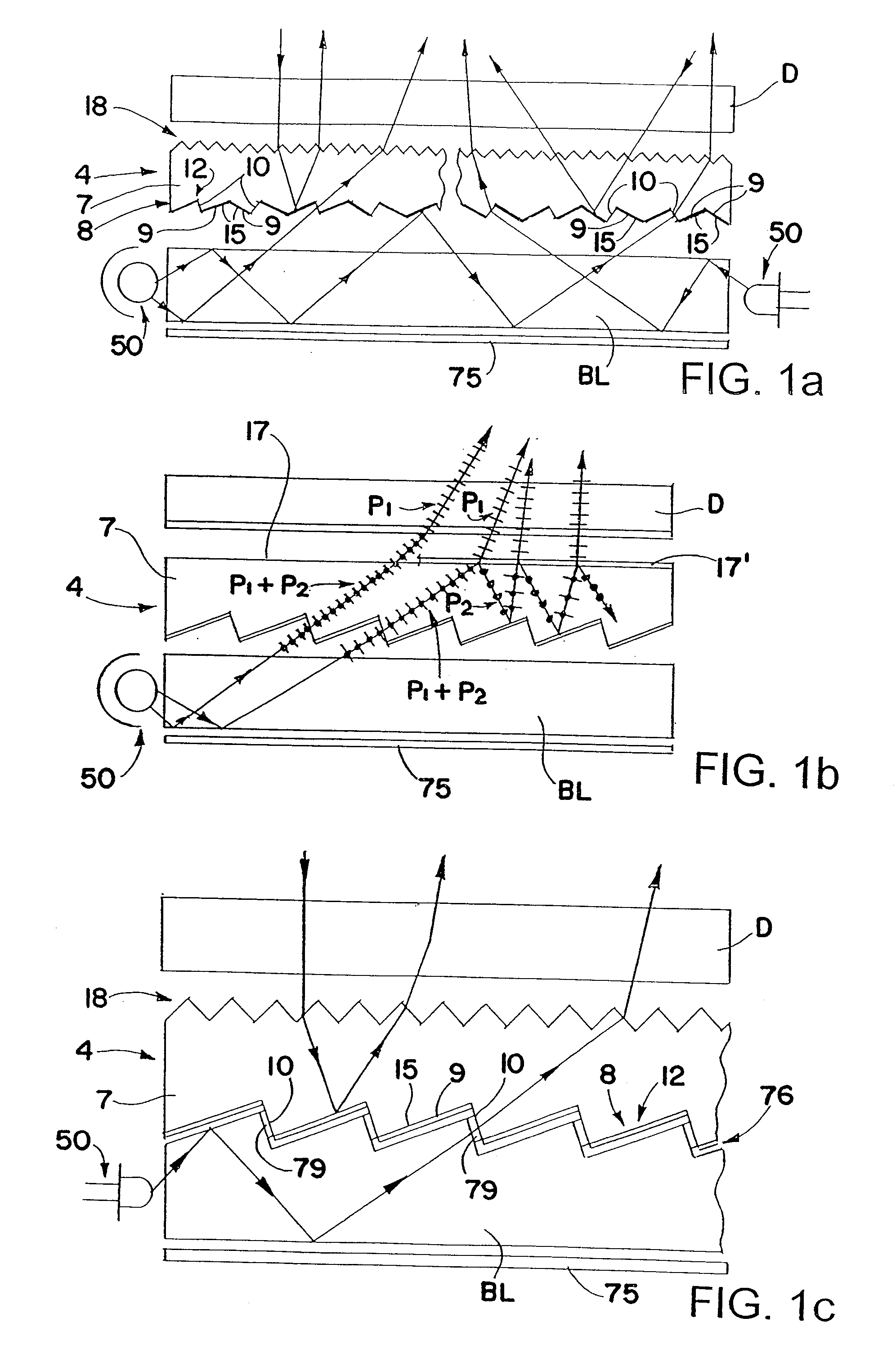
[0044]Referring now in detail to the drawings, and initially to FIGS. 1-3, these figures schematically show three different transreflector systems 1, 2 and 3 in accordance with this invention each including a transreflector 4, 5 and 6 placed between a display D such as a liquid crystal display or membrane switch and a backlight BL for reflecting more of the ambient light that passes through the display back out the display making it more visible (e.g., brighter) in a lighted environment, and for transmitting more of the light from the backlight through the transreflector and out the display to illuminate the display in a dark environment.

[0045]Each of the transreflectors 4, 5 shown in FIGS. 1 and 2 comprises a transparent (i.e., optically transparent or translucent) substrate 7 which may be a plate or film including a multilayer film comprising for example a carrier film and an ultra-violet curable layer. On or in one side of the substrate are a plurality of spaced optical elements ...


PUM


Abstract

Optical assembly includes a hollow backlight having at least one light input edge and at least one light source positioned adjacent to the at least one light input edge. A back reflector is positioned at or in close proximity to a first side of the hollow backlight for reflecting the light through the hollow backlight and out through a second side of the hollow backlight superimposed on the first side, and a reflective polarizer is positioned at or in close proximity to the second side of the backlight.

Description

CROSS-REFERENCE TO RELATED APPLICATIONS[0001]This application is a continuation of U.S. patent application Ser. No. 11 / 736,666, filed Apr. 28, 2007, which is a division of U.S. patent application Ser. No. 10 / 683,630, filed Oct. 10, 2003, which is a division of U.S. patent application Ser. No. 10 / 010,835, filed Dec. 5, 2001, now U.S. Pat. No. 6,827,456, dated Dec. 7, 2004, the entire disclosures of which are incorporated herein by reference.FIELD OF THE INVENTION[0002]This invention relates to transreflectors that reflect a greater portion of the light that strikes one side of the transreflectors and transmit a greater portion of the light that strikes the other side of the transreflectors or vice versa. Also, this invention relates to different methods of making transreflectors.BACKGROUND OF THE INVENTION[0003]A transreflector is an optical device that transmits part of the light that strikes it and reflects part of the light that strikes it. An example of a transreflector is a beam...

Claims


Application Information

Patent Timeline
IPC IPC(8): F21V13/08F21V5/00F21V8/00G02B5/08F21Y101/00F21Y101/02G02B5/02G02B6/00G02F1/1335G02F1/13357
CPCF21V5/00G02B6/0021G02B6/0036G02B6/0038G02B6/005G02F1/133615G02B6/0056G02B6/0061G02B6/0065G02B6/0073G02F1/133555G02B6/0053G02F1/1335F21V7/04F21V7/00
Inventor PARKER, JEFFERY R.MCCOLLUM, TIMOTHY A.
Owner INNOVATIVE DISPLAY TECH
Why Eureka
Try Eureka