Double-ended isolated dc-dc converter
a converter and isolated technology, applied in the direction of electric variable regulation, process and machine control, instruments, etc., can solve the problems of disadvantageous complex circuit configuration and difficulty in reducing the size and weight of the converter, and achieve the effect of high-efficiency power conversion
- Summary
- Abstract
- Description
- Claims
- Application Information
AI Technical Summary
Benefits of technology
Problems solved by technology
Method used
Image
Examples
first preferred embodiment
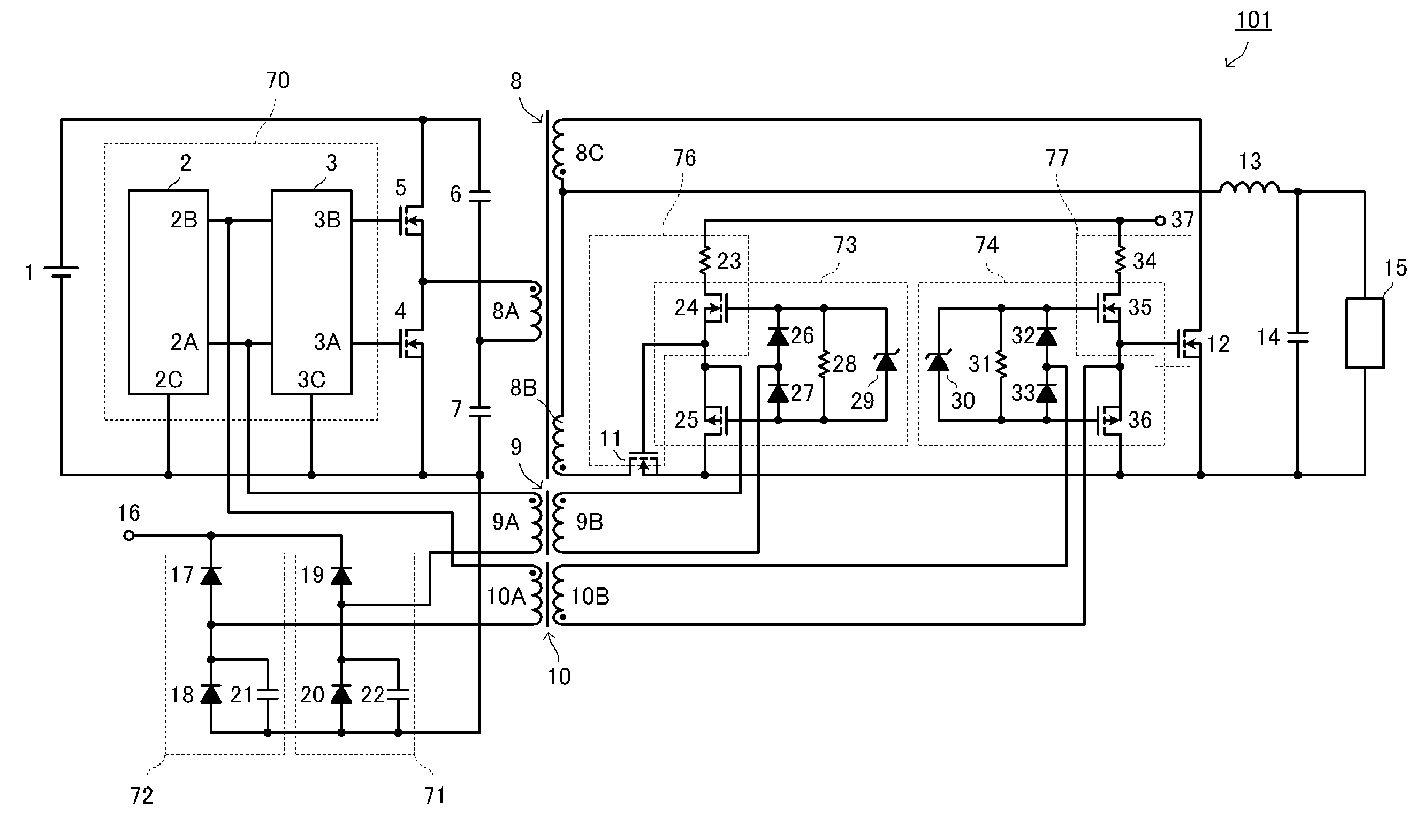
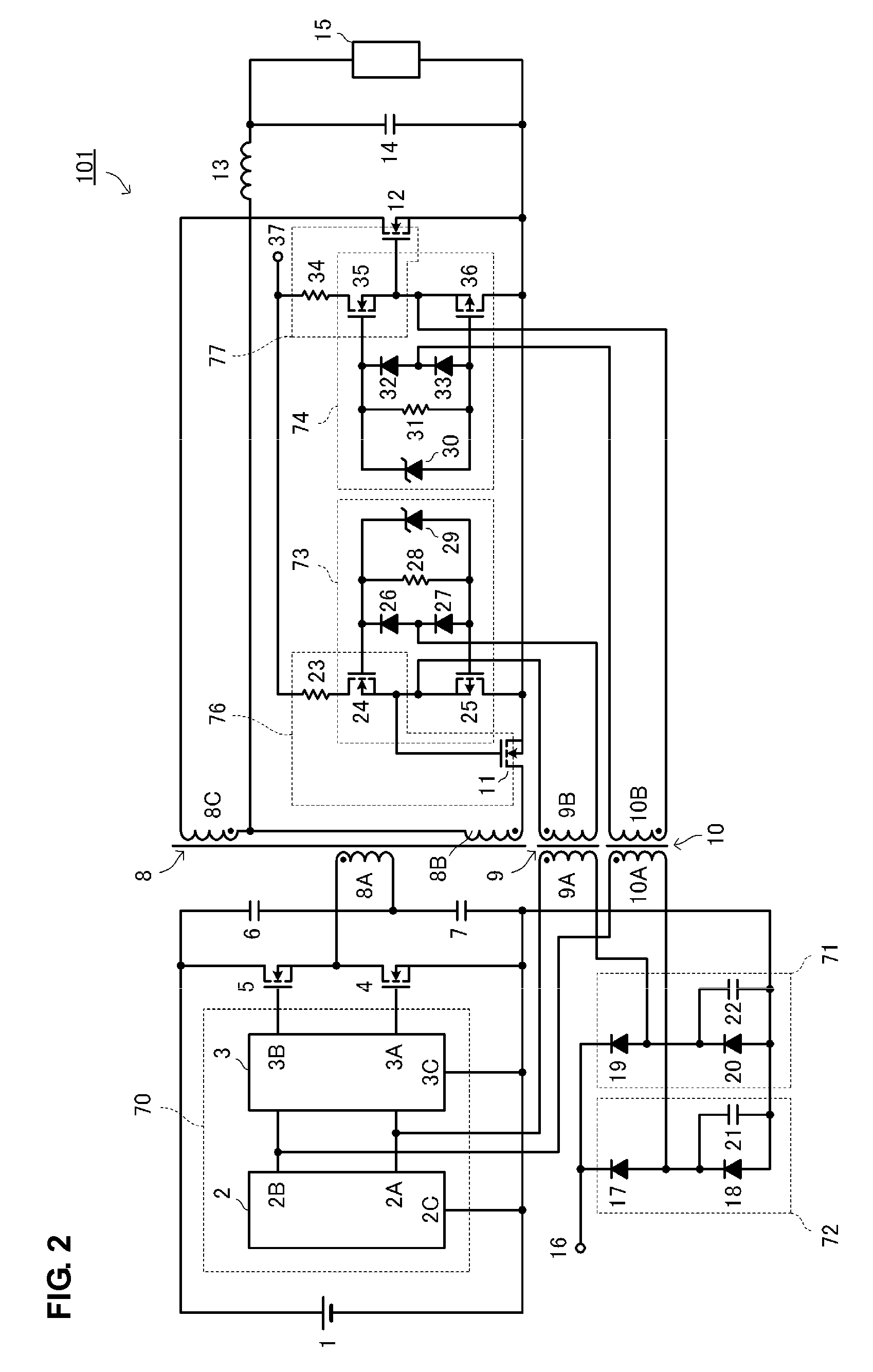
[0032]FIG. 2 is a circuit diagram of a double-ended isolated DC-DC converter according to a first preferred embodiment of the present invention. FIG. 3 is a waveform diagram of the main portion of the double-ended isolated DC-DC converter. FIGS. 4A to 4D are diagrams illustrating the structure of a transformer used in the first preferred embodiment.
[0033]As shown in FIG. 2, a double-ended isolated DC-DC converter 101 includes a main transformer 8 having a primary coil 8A and a secondary coil 8B, a first power switch 4 and a second power switch 5 connected to the primary side of the main transformer 8, a primary side control circuit 70 arranged to control switching operations of the first power switch 4 and the second power switch 5. The double-ended isolated DC-DC converter 101 further includes a first synchronous rectifier 11, a second synchronous rectifier 12, and a choke coil 13 connected to a secondary side of the main transformer 8.
[0034]The double-ended isolated DC-DC converte...
second preferred embodiment
[0080]FIG. 5 is a circuit diagram of a double-ended isolated DC-DC converter according to a second preferred embodiment of the present invention. The double-ended isolated DC-DC converter has a basic structure similar to that of the first preferred embodiment.
[0081]However, as shown in FIG. 5, a double-ended isolated DC-DC converter 102 includes a first synchronous rectifier side delay circuit 76 and a second synchronous rectifier side delay circuit 77 having a structure different from that illustrated in FIG. 2. In the preferred embodiment shown in FIG. 2, a gate charging current of the first synchronous rectifier 11 and the second synchronous rectifier 12 is restricted by the resistors 23 and 34 so that the turn-on timing points of the first synchronous rectifier 11 and the second synchronous rectifier 12 are delayed by third and fourth delay times K and L, respectively. Thus, the occurrence of a short-circuit current is prevented. However, due to variation in the input capacitanc...
third preferred embodiment
[0088]FIG. 6 is a circuit diagram of a double-ended isolated DC-DC converter according to a third preferred embodiment of the present invention.
[0089]In order to reduce a manufacturing cost, a double-ended isolated DC-DC converter 103 does not include the high side driver 3 shown in FIG. 2. Accordingly, the second power switch 5 having a reference potential (source) that is disconnected from the ground is driven using the second pulse transformer 10.
[0090]As shown in FIG. 6, in order to obtain driving power of the second power switch 5, a bootstrap circuit 54 including a capacitor 56 and a diode 55 is provided. A series circuit of an FET 58, an FET 59, and a resistor 57 is connected between an output unit of the bootstrap circuit 54 and the ground on a primary side. A connection point between the FET 58 and the FET 59 is connected to the gate of the second power switch 5. A circuit of diodes 60 and 61, a zener diode 63, and a resistor 62 is connected to the gates of the FET 58 and t...
PUM
 Abstract
Description
Claims
Application Information
 - R&D
- Intellectual Property
- Life Sciences
- Materials
- Tech Scout
- Unparalleled Data Quality
- Higher Quality Content
- 60% Fewer Hallucinations
Browse by: Latest US Patents, China's latest patents, Technical Efficacy Thesaurus, Application Domain, Technology Topic, Popular Technical Reports.
© 2025 PatSnap. All rights reserved.Legal|Privacy policy|Modern Slavery Act Transparency Statement|Sitemap|About US| Contact US: help@patsnap.com


