
Improved dual-auxiliary resonant pole-type three-phase soft switch inversion circuit

A technology of inverter circuit and auxiliary switch tube, which is used in electrical components, high-efficiency power electronic conversion, conversion of AC power input to DC power output, etc. And other issues

Active Publication Date: 2018-11-02
NORTHEASTERN UNIV
View PDF5 Cites 6 Cited by
  • Summary
  • Abstract
  • Description
  • Claims
  • Application Information

AI Technical Summary

Problems solved by technology

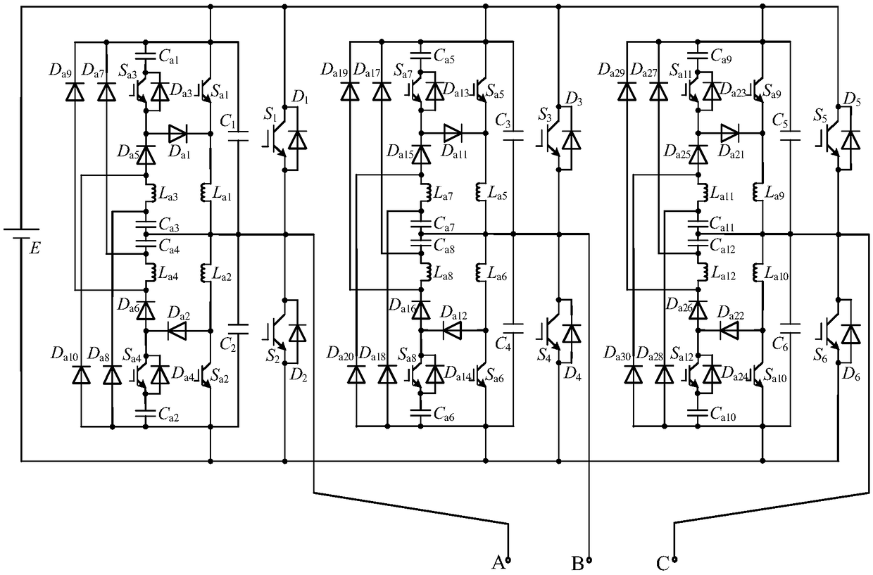
However, the inverter still has deficiencies: ① The auxiliary resonant commutation circuit of the inverter uses many devices and is too complicated. More devices not only mean the complexity of the circuit and the increase of the production cost, but also mean that the actual The number of possible fault points in the system increases, thereby increasing the potential safety hazard of the system; ②The auxiliary resonant commutation circuit of the inverter has two groups of resonant components coupled with each other, and the resonant commutation process is coupled with each other, and system oscillation is difficult to avoid; ③ The second set of auxiliary resonant capacitors of the inverter cannot be fully pre-charged under certain load conditions, resulting in an uncontrollable output voltage change rate at this time, which will bring extremely adverse effects in AC drive applications
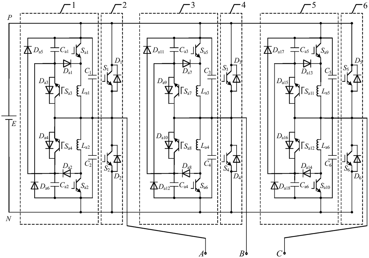
[0006] However, the inverter still has shortcomings: there is a contradiction between the voltage change rate when the main switching tube is turned off and the current stress of the auxiliary resonant commutation circuit, so that the main resonant capacitor and auxiliary resonant capacitor cannot be used in the parameter design of the inverter. The limit is small, so the current stress cannot reach the level approximately equal to the peak value of the load current, which makes the current stress and conduction loss of the double auxiliary resonant commutation circuit higher, reducing the conversion efficiency of the inverter

Method used


Image

  • Improved dual-auxiliary resonant pole-type three-phase soft switch inversion circuit
  • Improved dual-auxiliary resonant pole-type three-phase soft switch inversion circuit
  • Improved dual-auxiliary resonant pole-type three-phase soft switch inversion circuit

Examples


Embodiment Construction

[0062] The specific implementation manners of the present invention will be further described in detail below in conjunction with the accompanying drawings and embodiments. The following examples are used to illustrate the present invention, but are not intended to limit the scope of the present invention.

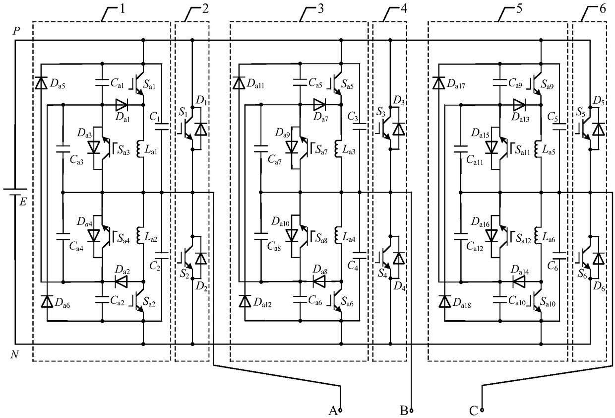
[0063] An improved dual-auxiliary resonant pole type three-phase soft-switching inverter circuit, such as image 3 As shown, including three-phase main inverter circuit and three-phase double auxiliary resonant converter circuit;

[0064] The three-phase main inverter circuit adopts a three-phase bridge circuit structure, including A-phase main inverter circuit 2, B-phase main inverter circuit 4 and C-phase main inverter circuit 6; the three-phase double auxiliary resonant converter circuit includes A-phase A dual auxiliary resonant commutation circuit 1 , a B-phase dual auxiliary resonant commutation circuit 3 and a C-phase dual auxiliary resonant commutation circuit 5 ....


PUM


Abstract

The invention provides an improved dual-auxiliary resonant pole-type three-phase soft switch inversion circuit, and relates to the technical field of power electronics. The circuit comprises three phase main inversion circuits and three phase dual-auxiliary resonant conversion circuits, wherein each phase main inversion circuit comprises two main switch tubes and two main diodes, and each phase dual-auxiliary resonant conversion circuit comprises four auxiliary switch tubes, two main resonant capacitors, four auxiliary resonant capacitors, two auxiliary resonant inductors and six auxiliary diodes. With the improved dual-auxiliary resonant pole-type three-phase soft switch inversion circuit provided by the invention, the simplification of the dual-auxiliary resonant conversion current and the decoupling of the resonant process are completed, meanwhile, the current stress of the dual-auxiliary resonant conversion circuit is approximate to a peak load current by additionally arranging twoauxiliary resonant capacitors for limiting voltage change rate, so that the conduction loss of the dual-auxiliary resonant conversion circuit can be effectively reduced, and high-efficiency electricenergy conversion of an inverter within a full load range is maintained.

Description

technical field [0001] The invention relates to the technical field of power electronics, in particular to an improved double-auxiliary resonant pole type three-phase soft-switching inverter circuit. Background technique [0002] Today, with more and more frequent power conversions, the application places of inverters are expanding day by day, and inverters can be seen in fields such as new energy power generation, motor drives, and uninterruptible power supplies. With the development of inverters, people's requirements for inverters are getting higher and higher, and inverters with high frequency, miniaturization, and light weight are more and more desired by people, and the introduction of soft switching technology is just in time. Soft switching technology can not only solve the switching loss problem caused by the increase of switching frequency, but also reduce electromagnetic noise (EMC) and electromagnetic interference (EMI), so as to create a safe, green and efficien...

Claims


Application Information

Patent Timeline
IPC IPC(8): H02M7/5387H02M1/44
CPCH02M1/44H02M7/53871H02M1/0058Y02B70/10
Inventor 褚恩辉谢昊霖李思包建群徐畅卢萍
Owner NORTHEASTERN UNIV
Learn More