Motion guide device, table apparatus, and damping method for motion guide device

a technology of motion guide device and table apparatus, which is applied in the direction of bearings, shafts and bearings, bearings, etc., can solve the problems of difficult damped, vibration may occur, and causes, and achieve the effect of reducing braking force, smooth damping of vibration, and increasing braking for

Inactive Publication Date: 2009-06-25
THK CO LTD
View PDF19 Cites 4 Cited by
  • Summary
  • Abstract
  • Description
  • Claims
  • Application Information

AI Technical Summary

Benefits of technology

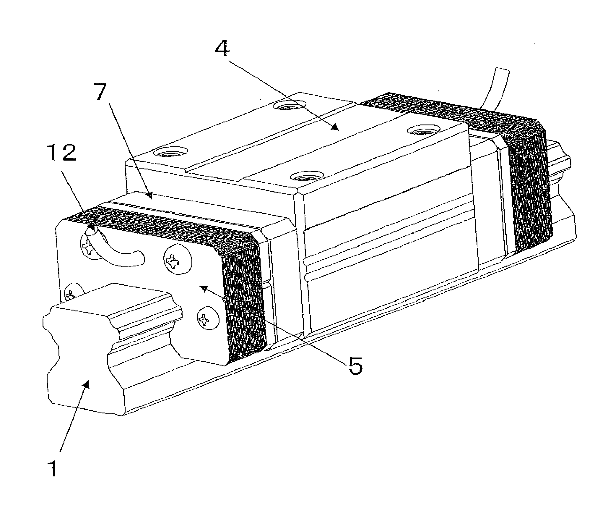
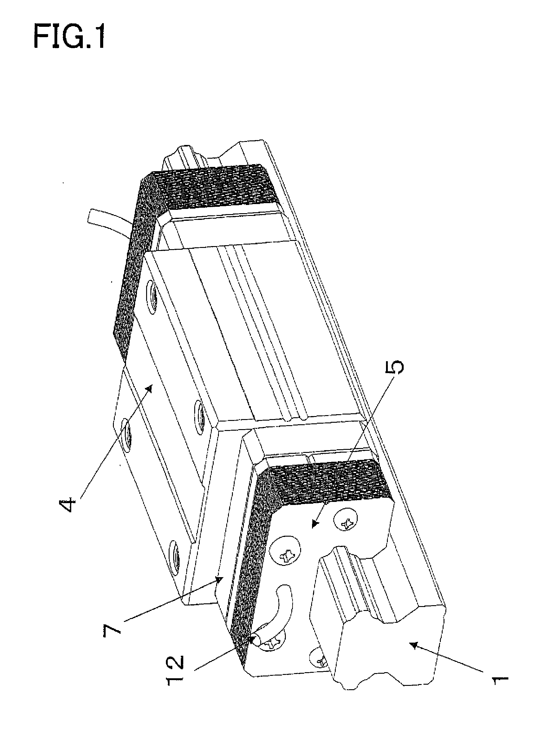
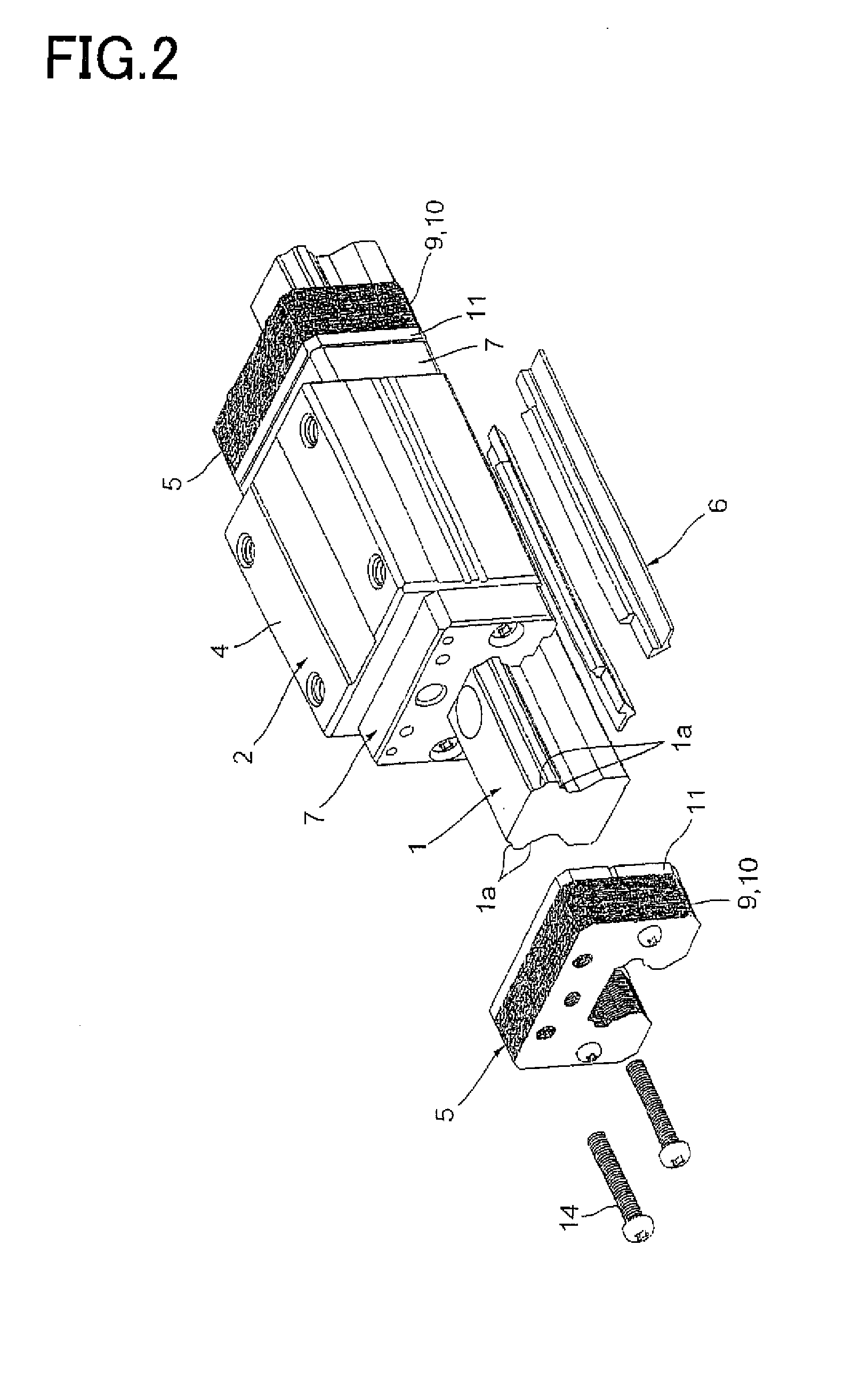
[0021]In the present invention according to claim 1, the viscosity resistance of the layer of the oil filled in the gap between the raceway member and the moving member gives the motion guide device a damping characteristic. Since the braking power is in proportion to the movement speed of the moving member, the braking power caused when the device starts remains to be smaller, while the braking power becomes higher with an increase in the movement speed of the moving member. Accordingly, for moving the moving member with the help of a motor, for instance, the braking force can be reduced so that a load applied to the motor is reduced. Meanwhile when the moving member stops and is about to vibrate, the braking force can be made larger to suppress and damp the vibration smoothly. In addition, so long as the oil is kept being supplied to the motion guide device, the device can be used semi-permanently as a device with the damping function. Hence it is avoidable that the disadvantage that damping the vibration is weakened as the time goes by, which is seen in contact seals.
[0022]In the present invention according to claim 2, the damping member is arranged as a member which is different from the moving block, so that it is easier to make the gap between the damping member and the raceway member. Because the viscosity resistance of the oil becomes larger as the oil layer is thinner, a larger braking force can be obtained by making the gap between the damping member and the raceway member thinner.
[0023]In a motion guide device in which a moving member makes linear or curbed movements along a raceway member, it is difficult to seal oil filled in a gap between the damping member and the raceway member, compared to the sealing in rotary bearings. In the present invention according to claim 3, the oil supply passage is formed for supplying oil to the gap between the damping member and the raceway member, whereby the oil can be filled into the gap even when the oil flows out of the gap.
[0024]In the present invention according to claim 4, the concavo-convex shape of the surface of the damping member gives the oil sticking to the damping member. Hence the damping member has an improved performance for retaining the oil, thereby reducing the amount of oil flowing out of the gap. By contrast, if the surface of the damping member which contacts the layer of oil is made flat, there is no means for giving sticking to the damping member, the oil retaining performance of the damping member is lessened.
[0025]In the present invention according to claim 5, it is possible to provide the end damping member with a concavo-convex surface to contact the layer of oil. In addition, when the end damping member is moved relatively to the raceway member, the oil can be retained by the end damping member.
[0026]In the present invention according to claim 6, the oil can be filled into the gap between the end damping member and the raceway member. Further, the slit is formed in the second plates with the gap from the raceway member is larger, so that it is easier to fill the oil into the gap between the end damping member and the raceway member. Still further, the slit is formed every two plates, which allows the oil to be filled in the entire gap with ease. And, compared to the structure in which the slit is formed in both the first and second plates, the amount of oil can be suppressed, with the oil still supplied at an appropriate amount.

Problems solved by technology

However, at the same time, the rolling guide cannot generate a damping force like friction resistance caused in the sliding guide, so that there is a disadvantage that vibration, once caused, is difficult to be damped.
When a moving member is moved to a target position and then stopped thereat, the vibration will occur due to the inertia of the moving member and, even during movement of the moving member, the vibration may occur.

Method used


Image

  • Motion guide device, table apparatus, and damping method for motion guide device
  • Motion guide device, table apparatus, and damping method for motion guide device
  • Motion guide device, table apparatus, and damping method for motion guide device

Examples


embodiment

[0107]The following “numeral 1” formula indicates how to calculate the viscosity resistance of oil. FIG. 22 shows a model of parameters employed by this calculation formula.

v(1 / s)=V(m / s)h(m)τ(Pa)=F(N)A(m2)η(Pa·s)=τ(Pa)v(1 / s)ɛ(mm2 / s)=η(Pa·s)103ρ(g / cm3),accordingly,F(N)=η(Pa·s)·A(m2)·V(m / s)h(m)=ɛ(mm2 / s)·ρ(g / cm3)·A(m2)·V(m / s)·103h(m),[Numeral1]

where γ is a shear rate, V is a speed, h is a height, τ is a shear strain, F is a viscosity resistance, A is a contact area, η is a viscosity, ε is a kinetic viscosity, and ρ is a density.

[0108]One of the parameters having an influence on the viscosity resistance F is the speed V. The faster the movement speed of the moving member 2, the larger the viscosity resistance F. The height h is the height of a layer of oil, that is, the width of the gap 16 between each end damping member 5 and the raceway rail 1. The narrower the gap 16, the larger the viscosity resistance F. In addition, the larger the contact area A, the larger the viscosity resistanc...


PUM


Abstract

A motion guide device that has a novel damping structure different from the conventional damping structure is provided. The present invention comprises a raceway member (1) having a rolling-element rolling part (1a); a moving member (2) having a loaded rolling-element rolling part (2a) facing the rolling-element rolling part (1a) and being allowed to make a linear or curved movement relatively to the raceway member (1); and a plurality of rolling elements (3) intervening between the rolling-element rolling part (1a) of the raceway member (1) and the loaded rolling-element rolling part (2a) of the moving part (2). A gap (16) between the raceway member (1) and the moving member (2) is filled with a layer of oil contacting the raceway member (1) and the moving member (2). Viscosity resistance of the oil is utilized to apply a braking force to the moving member (2) or the raceway member (1) in proportion to a speed.

Description

TECHNICAL FIELD[0001]The present invention relates to motion guide devices, such as liner guides, ball splines, and ball screws, in which there are a raceway member, a moving member and rolling members, such as balls and rollers, intervening between the raceway member and the moving member.BACKGROUND ART[0002]Like a table making a linear movement on a frame of a machine, rolling-guide type of motion guide devices have now been put to use, in which rolling elements, including balls or rollers, are arranged in a guide portion subjected to a liner movement, are used to provide a guide function with the aid of rolling motions of the rolling elements. This rolling-guide type of motion guide device is equipped with a raceway rail forming a track for motions of a moving member, a moving block moving relatively to the raceway rail, and rolling elements disposed to intervene between the raceway rail and the moving block.[0003]Compared to sliding guide, the rolling guide has various advantage...

Claims


Application Information

Patent Timeline
Patent Type & Authority Applications(United States)
IPC IPC(8): F16C29/02
CPCF16C29/00F16C29/088F16C29/086F16C29/0647F16C29/06
Inventor MICHIOKA, HIDEKAZUYOSHINO, MASAHIKOHOMMA, MITSUAKINAGAI, SATORU
Owner THK CO LTD
Why Eureka
Try Eureka