Tubular Fuel Cell Module and Manufacturing Method Thereof

a technology of tubular fuel cells and fuel cells, which is applied in the manufacture of final products, cell components, electrochemical generators, etc., can solve the problems of less reliable seals in tubular pefcs, complex seal structures, etc., and achieve the effect of improving seal reliability

Inactive Publication Date: 2009-06-25
TOYOTA JIDOSHA KK
View PDF4 Cites 11 Cited by
  • Summary
  • Abstract
  • Description
  • Claims
  • Application Information

AI Technical Summary

Benefits of technology

[0009]This invention thus provides a tubular fuel cell module having improved seal reliability, as well as a manufacturing method of that tubular fuel cell module.

Problems solved by technology

As a result, the seal in a tubular PEFC having a complex seal structure in which there are many seal portions tends to be less reliable.

Method used


Image

  • Tubular Fuel Cell Module and Manufacturing Method Thereof
  • Tubular Fuel Cell Module and Manufacturing Method Thereof
  • Tubular Fuel Cell Module and Manufacturing Method Thereof

Examples


Embodiment Construction

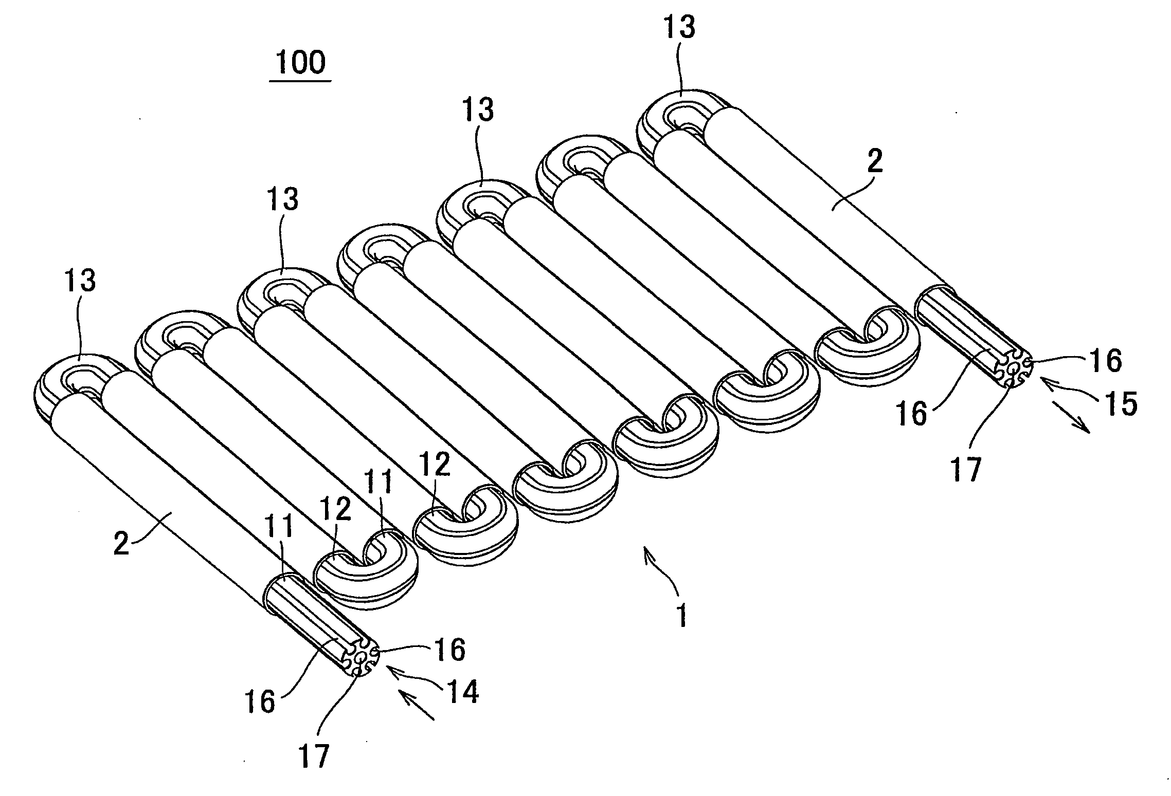
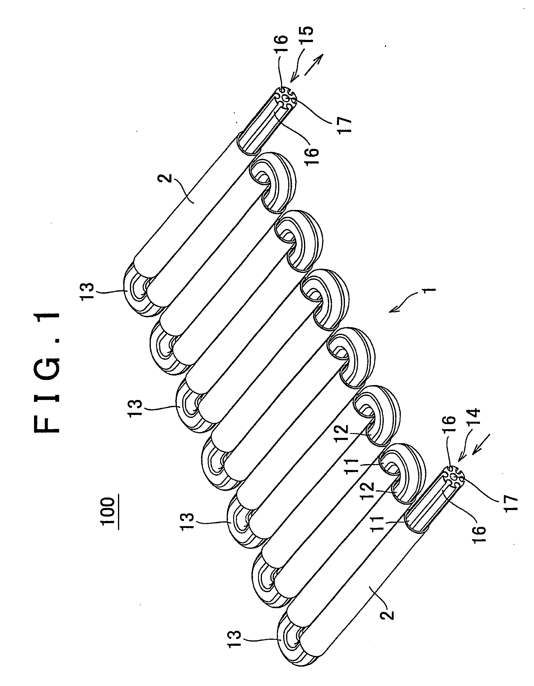
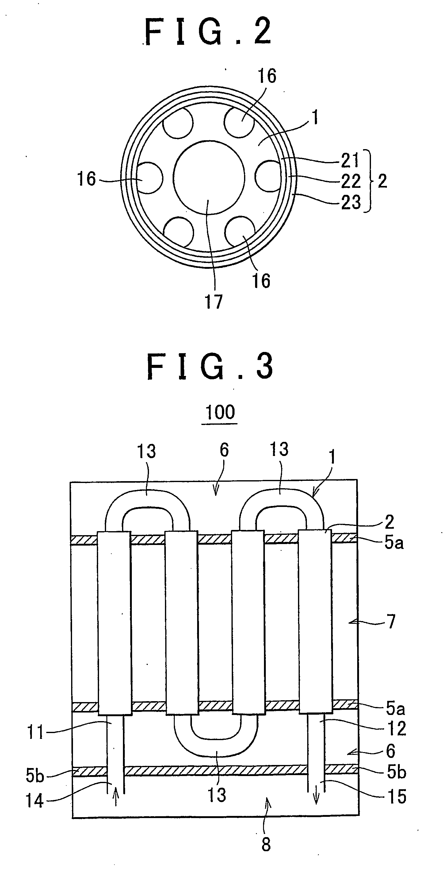
[0041]A heat transfer pipe through which a heating / cooling medium flows is provided in a tubular PEFC module in order to keep the temperature of tubular cells within an appropriate range. In a related tubular PEFC module (hereinafter simply referred to as “related module”), the heat transfer pipe is straight. As a result, the number of locations where the heat transfer pipe passes through a seal portion or seal member (which will be described later) formed between a reaction gas diffusion region and a heating / cooling medium diffusion region is equal to the number of heat transfer pipes, which makes the seal structure complex. That is, in the related module, the heat transfer pipe passes through the seal portion at many locations so the distance between those locations is very short. As a result, the seal structure tends to be complex, which tends to reduce the reliability of the seal and thus the stability of the tubular PEFC system (hereinafter simply referred to as “system”). One ...


PUM

PropertyMeasurementUnit
temperatureaaaaaaaaaa
angleaaaaaaaaaa
angleaaaaaaaaaa

Abstract

A tubular fuel cell module is provided with a tubular cell of a tubular fuel cell, and a heat transfer pipe through which a heating/cooling medium flows to selectively heat and cool the tubular fuel cell. The heat transfer pipe includes a first straight portion, a second straight portion, and a bent portion that connects the first straight portion with the second straight portion. At least a portion of the tubular cell is arranged on at least one of the first straight portion and the second straight portion. As a result, the reliability of a seal of the tubular fuel cell module is improved.

Description

BACKGROUND OF THE INVENTION[0001]1. Field of the Invention[0002]The invention relates to a tubular fuel cell module and a manufacturing method thereof. More particularly, the invention relates to a tubular fuel cell module having improved seal reliability and a manufacturing method of that tubular fuel cell module.[0003]2. Description of the Related Art[0004]In recent years much research has been done with tubular fuel cells (hereinafter also referred to as “tubular PEFC”) with an aim to improve output density per unit volume to at least a certain level. The unit cell of a tubular PEFC (hereinafter also referred to as “tubular cell”) typically includes a Membrane Electrode Assembly (MEA) which has a hollow electrolyte layer and a catalyst layer arranged on both sides (i.e., the inside and the outside) of that hollow electrolyte layer. Electric energy which is generated through an electrochemical reaction induced by supplying a gas containing hydrogen to the inside of the MEA and a g...

Claims


Application Information

Patent Timeline
Patent Type & Authority Applications(United States)
IPC IPC(8): H01M8/12H01M8/10
CPCH01M8/004H01M8/0267H01M8/04029Y02E60/521H01M8/1006H01M8/241H01M8/2465H01M8/04074H01M8/0258Y02E60/50Y02P70/50
Inventor NAKANISHI, HARUYUKIMURATA, SHIGEAKIIMANISHI, MASAHIROTAMURA, YOSHIHISA
Owner TOYOTA JIDOSHA KK
Why Eureka
Try Eureka