
Lever type connector

Active Publication Date: 2009-06-25
YAZAKI CORP
View PDF5 Cites 2 Cited by
  • Summary
  • Abstract
  • Description
  • Claims
  • Application Information

AI Technical Summary

Benefits of technology

[0009]The invention has been made to solve the aforementioned problem, and is to provide a lever type connector capable of easily assembling a lever without excessively widening a lever side plate using an exclusive jig since it is possible to easily align a swing hole and a swing fulcrum protrusion.
[0013]According to the first aspect of the invention, it is possible to align the guide slope with the swing fulcrum protrusion on the connector housing side by swinging the lever about the rib as a fulcrum with the notch portion of the lever engaged with the rib of the connector housing. Then, it is possible to mount the lever side plate on the swing fulcrum protrusion according to the operation of the guide slope by swinging the lever, and subsequently it is possible to fit the swing hole to the swing fulcrum protrusion. Accordingly, it is unnecessary to perform alignment while excessively widening the lever side plate using an exclusive jig, and thus it is possible to easily fit the swing hole of the lever side plate to the swing fulcrum protrusion of the connector housing with minimum load. Therefore, workability of assembly is improved, and thus it is possible to assemble the lever in the air with one touch.
[0014]According to the second aspect of the invention, even when two swing fulcrum protrusions are arranged transversely, the guide slope can come into contact with the swing fulcrum protrusion (on the base end side) close to the operation portion connecting the pair of lever side plates to each other. Accordingly, since it is possible to mount the lever side plate on the swing fulcrum protrusion, and thus it is possible to open the lever side plate outward. In this case, with respect to the swing fulcrum protrusion provided away from the operation portion of the lever, the lever side plate is more widely opened, and thus it is possible to easily fit the swing hole without the guide slope. Therefore, the minimum number of guide slopes may be provided.
[0015]According to the third aspect of the invention, since it is possible to keep the lever before connector fitting at the temporary locking position, it is possible to smoothly perform the fitting operation of the connector by the operation of the lever from the temporary locking state in which the position of the cam mechanism is matched.

Problems solved by technology

However, when one end side of a pair of lever side plates is bent and opened to fit the swing hole to the swing fulcrum protrusion, it is necessary to align the swing hole and the swing fulcrum protrusion while excessively widening the lever side plate using an exclusive jig.
Accordingly, workability of assembly is poor.

Method used


Image

  • Lever type connector
  • Lever type connector
  • Lever type connector

Examples


Embodiment Construction

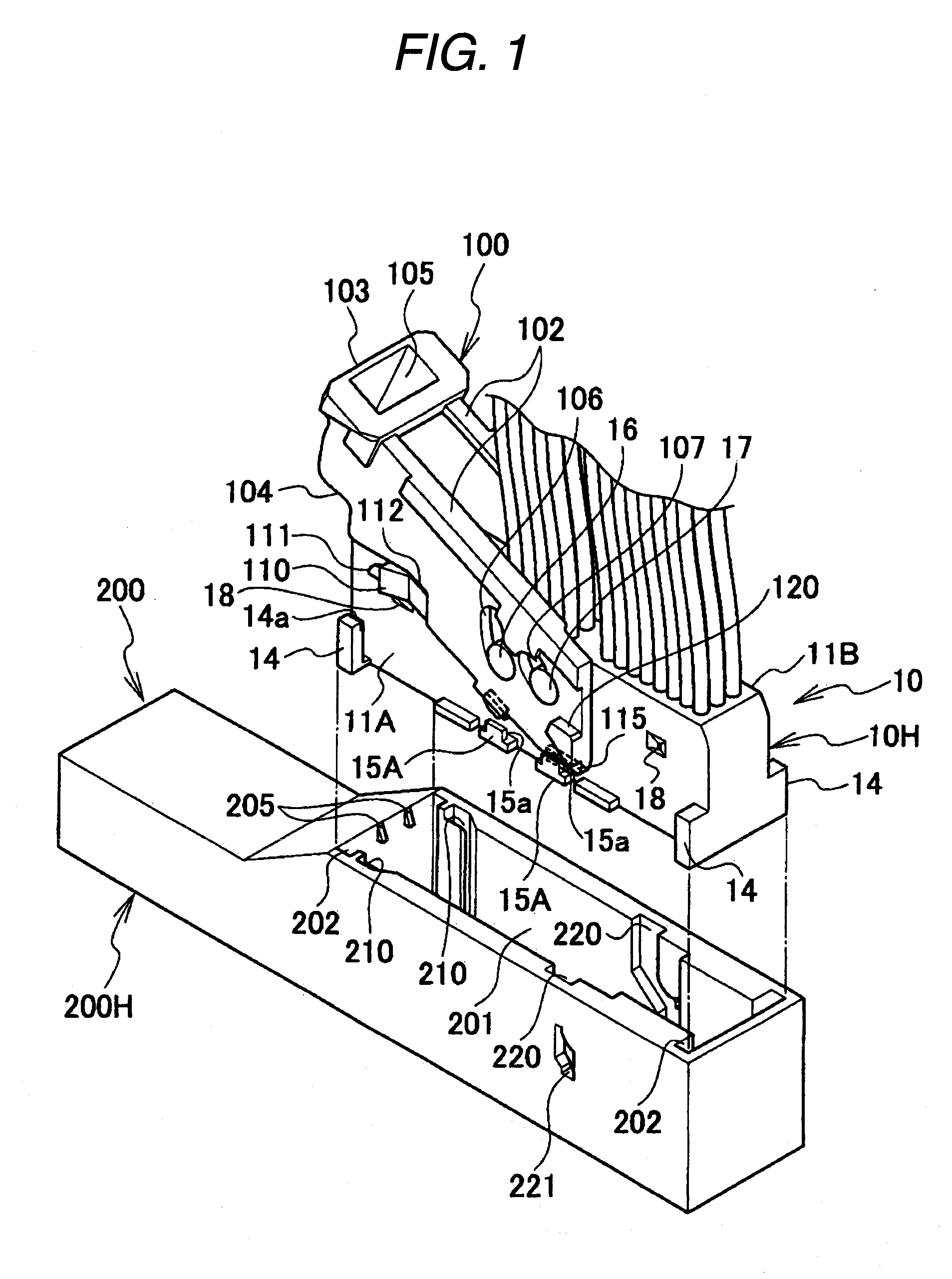
[0030]Hereinafter, an embodiment of the invention will be described with reference to the drawings.

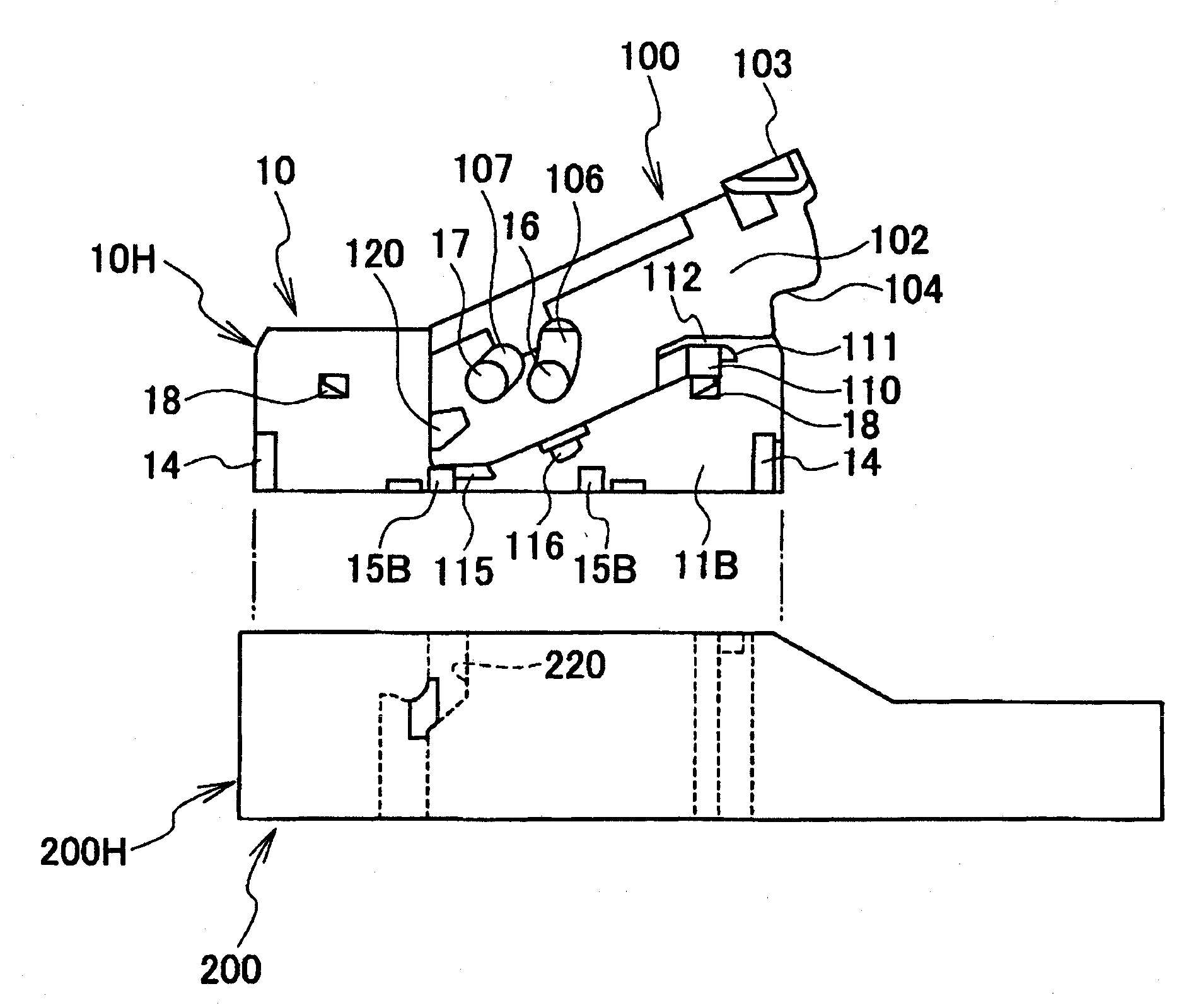
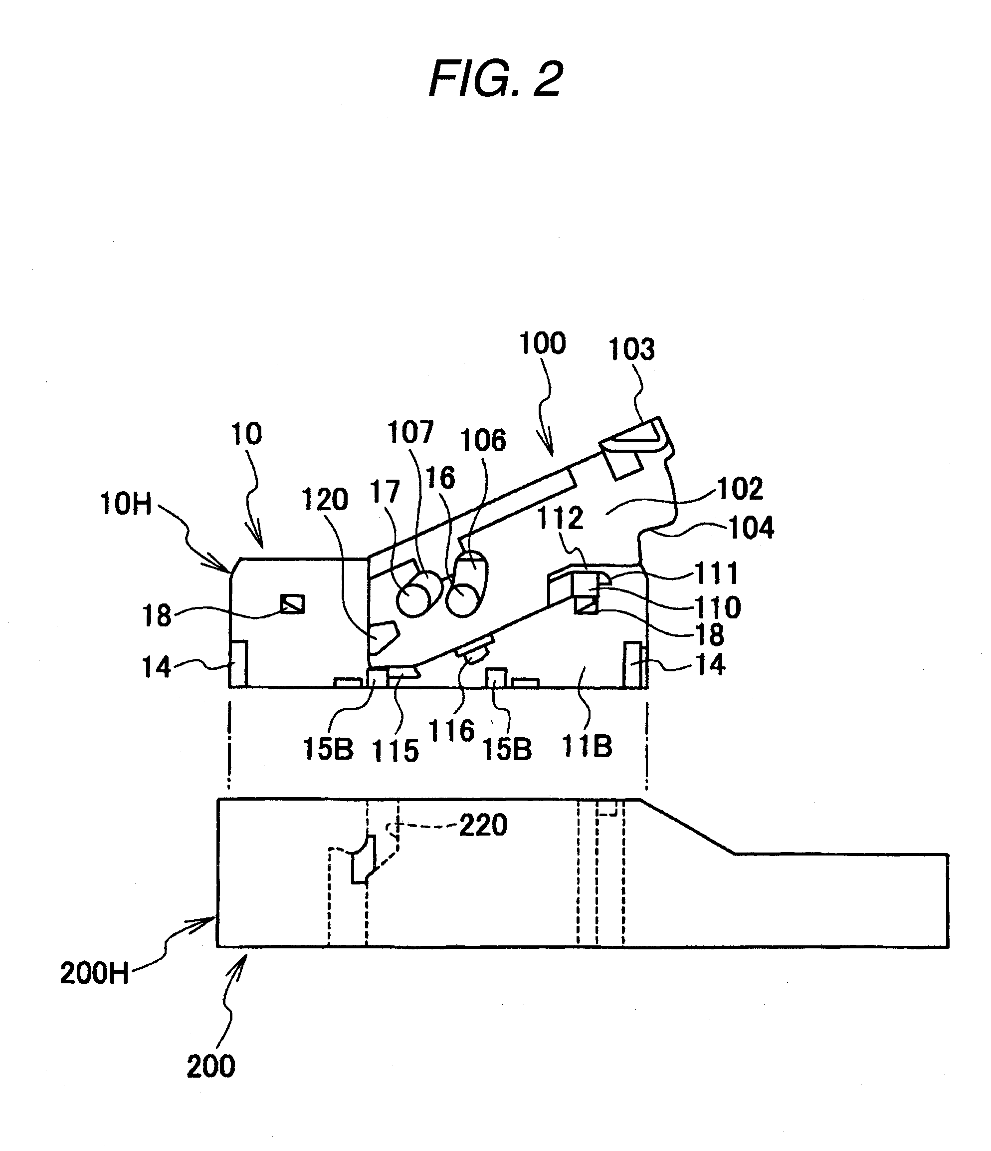
[0031]FIG. 1 is a perspective view illustrating a state before fitting of a lever type connector according to an embodiment, FIG. 2 is a side view as viewed from the side opposite to FIG. 1, FIG. 3 is a perspective view as viewed from the bottom of a lever, FIG. 4 is a transverse-sectional view illustrating a part provided with a guide slope of the lever, FIG. 5 is a side view illustrating a first step of mounting the lever on a male connector housing, FIG. 6 is a side view illustrating a state of slightly swinging the lever from the state shown in FIG. 5, FIG. 7 is a schematic plan view as viewed from the top in the state shown in FIG. 6, FIG. 8 is a side view illustrating a state before swinging the lever to a temporary locking position in the state of mounting the lever on the male connector, FIG. 9 is a side view as viewed from the side opposite to FIG. 8, FIG. 10 is a side view il...


PUM


Abstract

Provided is a lever type connector for fitting a connector by a swing operation of a lever 100, in which a notch portion 104 is provided at lever side plates of a substantially U-shaped lever, and it is possible to mount the lever on a male connector housing while swinging the lever about a rib as a fulcrum by engaging the notch portion with a male connector housing rib 14. When swing fulcrum protrusions 16 and 17 and swing holes 106 and 107 are fitted to each other by swinging the lever about the rib as a fulcrum in an inner face of an outer peripheral portion of the lever side plate, the lever side plate is led to be mounted on the swing fulcrum protrusion to promote the lover side plate to open outward. A guide slope 108 thereby guiding the swing holes to be fitted to the swing fulcrum protrusions is provided.

Description

BACKGROUND OF THE INVENTION[0001]1. Field of the Invention[0002]The invention relates to a lever type connector capable of fitting or separating female and male connector housings with little force by a swing operation of a lever.[0003]2. Description of the Related Art[0004]A lever type connector is provided with a lever that is swingably mounted on one connector housing of a pair of connector housings fitted to each other, and help both connector housings to be fitted and separated by an operation of a cam mechanism provided between the lever and the other connector housing, by a swing operation of the lever.[0005]For example, a lever of a lever type connector described in Patent Document 1 has a swing hole on one end side of a pair of left and right lever side plates, and has a substantially U shape having an operation portion connecting both lever side plates to each other on the other side of the lever side plates. The lever has a cam protrusion (or cam groove) engaged with a ca...

Claims


Application Information

Patent Timeline
IPC IPC(8): H01R13/629
CPCH01R13/62955H01R13/62938
Inventor MATSUMURA, KAORUTSURUTA, AKIHIRO
Owner YAZAKI CORP
Features
  • Generate Ideas
  • Intellectual Property
  • Life Sciences
  • Materials
  • Tech Scout
  • Unparalleled Data Quality
  • Higher Quality Content
  • 60% Fewer Hallucinations
Learn More