Vehicle verification apparatus and vehicle control system using the same

a vehicle verification and control system technology, applied in the direction of brake systems, instruments, transportation and packaging, etc., can solve the problem of inability to correctly detect malfunctions, and achieve the effect of eliminating the complication of a redundancy system

Inactive Publication Date: 2009-06-25
DENSO CORP
View PDF34 Cites 23 Cited by
  • Summary
  • Abstract
  • Description
  • Claims
  • Application Information

AI Technical Summary

Benefits of technology

[0010]The present invention has been made in order to solve the problem mentioned above, and has as its object to provide a vehicle verification apparatus which is able to verify as to the correctness of the behavior control performed by a control unit for a controlled object and is able to eliminate complication of a redundancy system of each control unit, and to provide a vehicle control system using the vehicle verification apparatus.

Problems solved by technology

However, such a configuration in which control units that control the behaviors of controlled objects carry out mutual- or self-detection of the malfunction, raises a problem that malfunction cannot be correctly detected when the control units per se have malfunction.

Method used


Image

  • Vehicle verification apparatus and vehicle control system using the same
  • Vehicle verification apparatus and vehicle control system using the same
  • Vehicle verification apparatus and vehicle control system using the same

Examples


first embodiment

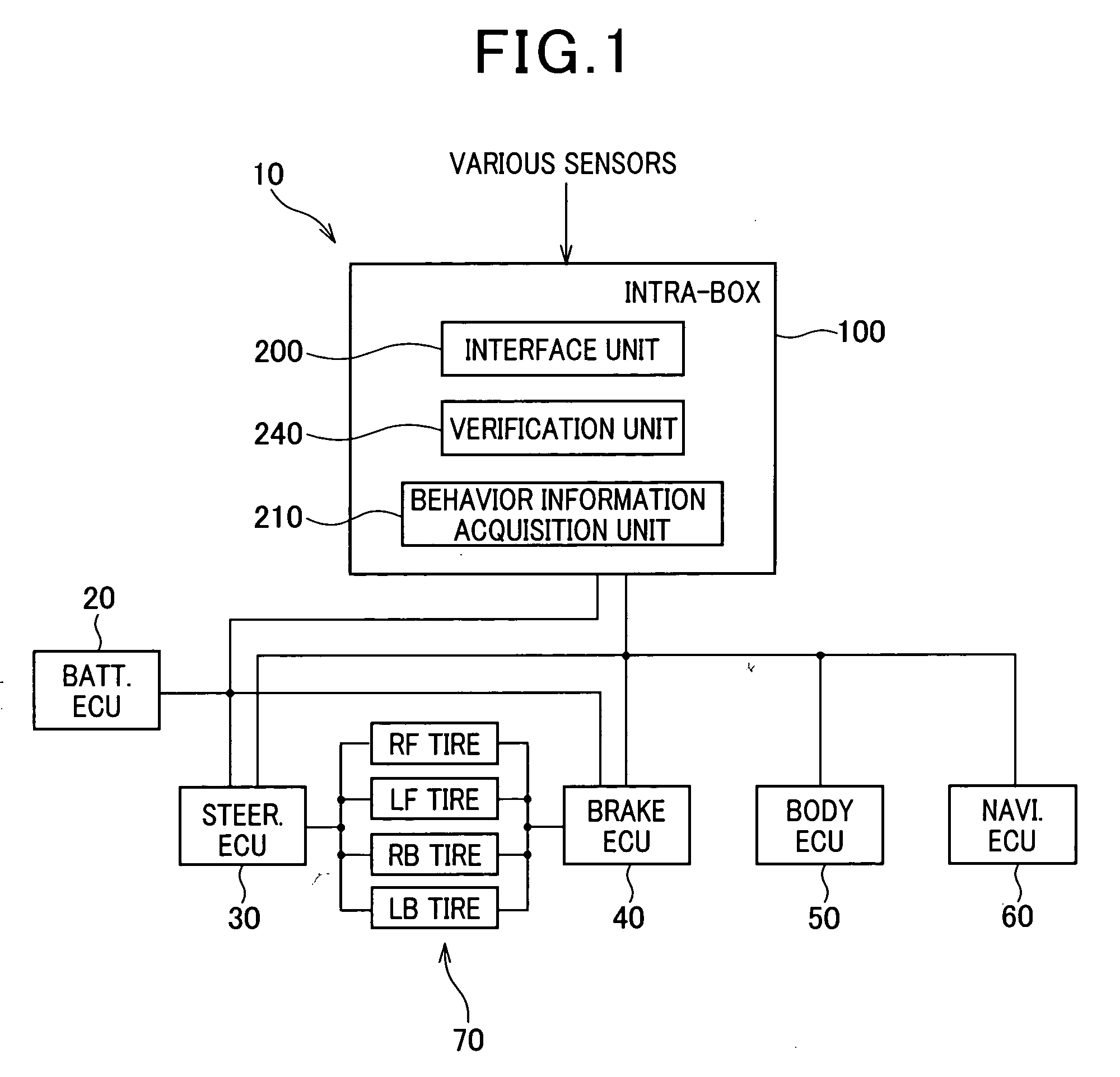
[0069]Referring to FIGS. 1-10, a first embodiment of the present invention will now be described. FIG. 1 illustrates a vehicle control system using a vehicle verification apparatus according to a first embodiment of the present invention.

[0070]A vehicle control system 10 includes a battery ECU (electronic control unit) 20, a steering ECU 30, a brake ECU 40, a body ECU 50, a navigation ECU 60, and a processor called intra-box 100 which operates based on a computer system. The battery ECU 20, the steering ECU 30, the brake ECU 40, the body ECU 50 and the navigation ECU 60 carry out behavior control for the controlled objects, covering the respective functional domains, that is, battery control, steering control, brake control, body control, and navigation control.

[0071]The battery ECU 20, the steering ECU 30, the brake ECU 40, the body ECU 50 and the navigation ECU 60 correspond to the control units recited in the claims. The control units control behaviors of targets to be controlled...

second embodiment

[0148]With reference to FIG. 11, hereinafter is described a vehicle control system using a vehicle verification apparatus according to a second embodiment of the present invention. In a vehicle control system 14 according to the second embodiment, a vehicle verification apparatus is configured by a plurality of intra-boxes 290, 300, rather than a single intra-box.

[0149]In FIG. 11, the two intra-boxes 290, 300 are disposed in the vehicle being distanced from each other. The intra-box 290 is disposed at the front of the vehicle to chiefly control the behavior of the controlled objects located at the front of the vehicle. The intra-box 300 is disposed at the rear of the vehicle to chiefly control the behavior of the controlled objects located at the rear of the vehicle. The intra-boxes 290, 300 include verification units 292, 302, behavior information acquisition units 294, 304, and majority determination units 296, 306, respectively.

[0150]Thus, if one of the intra-boxes has been damag...


PUM


Abstract

A verification apparatus is mounted in a vehicle, which is provided with targets to be controlled and a plurality of control units that control behaviors of the targets every functional domain of the vehicle, The verification apparatus comprises an acquisition unit and an verification unit. The acquisition unit acquires behavior information indicative of a behavior of a vehicle. The verification unit is provided independent of the control units. This verification unit uses the behavior information to verify correctness of the control of the behavior from the control units to the targets.

Description

CROSS-REFERENCE TO RELATED APPLICATION[0001]This application is based on and claims the benefit of priority from earlier Japanese Patent Application No. 2007-329106 filed Dec. 20, 2007, the description of which is incorporated herein by referenceBACKGROUND OF THE INVENTION[0002]1. Technical Field of the Invention[0003]The present invention relates to a vehicle verification apparatus for verifying as to the correctness of the behavior control performed by control units with respect to respective controlled objects loaded on the vehicle, and to a vehicle control system using the vehicle verification apparatus.[0004]2. Related Art[0005]Vehicle control systems have been known as disclosed, for example, In Japanese Patent Laid-Open Publication Nos. 2006-297994, 2004-122943, 2006-290168 and 2005-291173. In such a vehicle control system, the behavior of a controlled object loaded on the vehicle is controlled for every functional domain such as of a drive system or a control system.[0006]Th...

Claims


Application Information

Patent Timeline
Patent Type & Authority Applications(United States)
IPC IPC(8): G06F7/00B60T8/1755B60W10/18B60W10/184B60W10/20B60W40/10B60W50/02B60W50/04B62D6/00
CPCB60W10/184B60W10/20B60W30/02B60W30/18172B60W40/10B60W40/12G07C5/085B60W50/04B60W50/08B60W2050/021B62D5/0481B62D5/0484B60W50/02
Inventor TAKEDA, TOSHIHIKO
Owner DENSO CORP
Why Eureka
Try Eureka