
Solar system automatic sizing and failure identification on location using resident GPS receiver

a solar system and receiver technology, applied in the field of global positioning systems (gps), can solve the problems of difficult observation and verification of the operation of the appliance, prolonged time for the appropriate personnel, and compromise the performance of the appliance under all conditions, etc., and achieve the effect of quick identification and repair

Inactive Publication Date: 2009-06-25
BEARS JAMES +1
View PDF5 Cites 28 Cited by
  • Summary
  • Abstract
  • Description
  • Claims
  • Application Information

AI Technical Summary

Benefits of technology

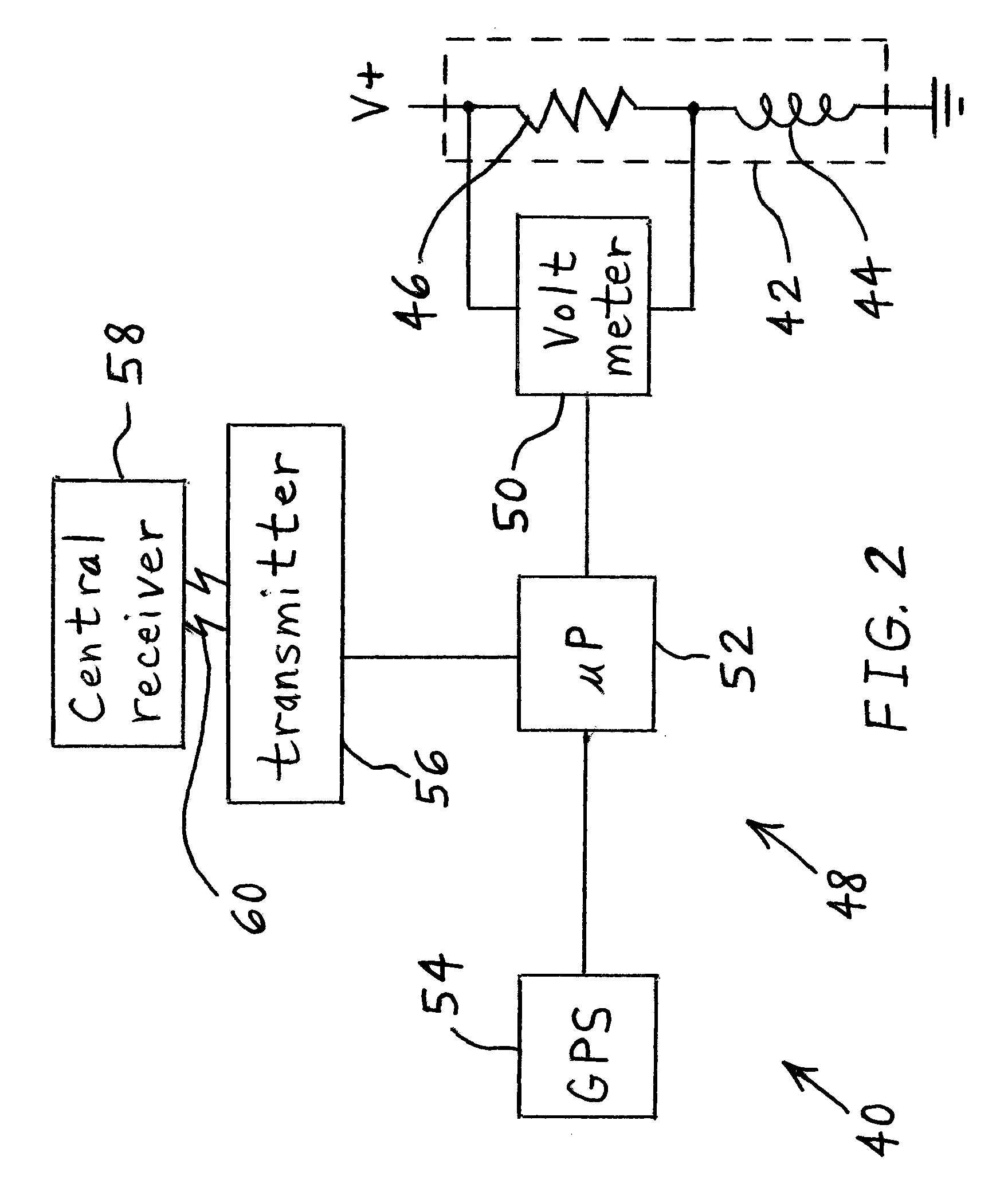
[0012]The invention comprises, in yet another embodiment thereof, a sensing method including providing a sensor to detect an event. A current location of the sensor is ascertained by use of a global positioning system device. Electrical power is supplied to the sensor and / or the global positioning system device by use of a solar collector. A radio frequency signal is transmitted to a central receiver when the sensor detects the event. The signal includes the current location of the sensor. An advantage of the present invention is that the current draw of an appliance may be set to a level that matches the power sourcing capability of an associated solar collector.
[0013]Another advantage is that street lights that have failed, or are about to fail, may be quickly identified and repaired.
[0014]Yet another advantage is that the exact location of a sensed event may be determined by use of a mobile sensor.

Problems solved by technology

However, maintaining the current draw of the appliance at a low level may compromise the performance of the appliance under all conditions.
Street lights, however powered, are typically widely geographically dispersed, and thus their operation is difficult to observe and verify.
Because of the difficulty of monitoring street lights, if a street light fails, it may take an extended period of time for the appropriate personnel to learn of the failure, identify its location, and determine what parts are required to make the repair.

Method used


Image

  • Solar system automatic sizing and failure identification on location using resident GPS receiver
  • Solar system automatic sizing and failure identification on location using resident GPS receiver
  • Solar system automatic sizing and failure identification on location using resident GPS receiver

Examples


Embodiment Construction

[0019]The embodiments hereinafter disclosed are not intended to be exhaustive or limit the invention to the precise forms disclosed in the following description. Rather the embodiments are chosen and described so that others skilled in the art may utilize its teachings.

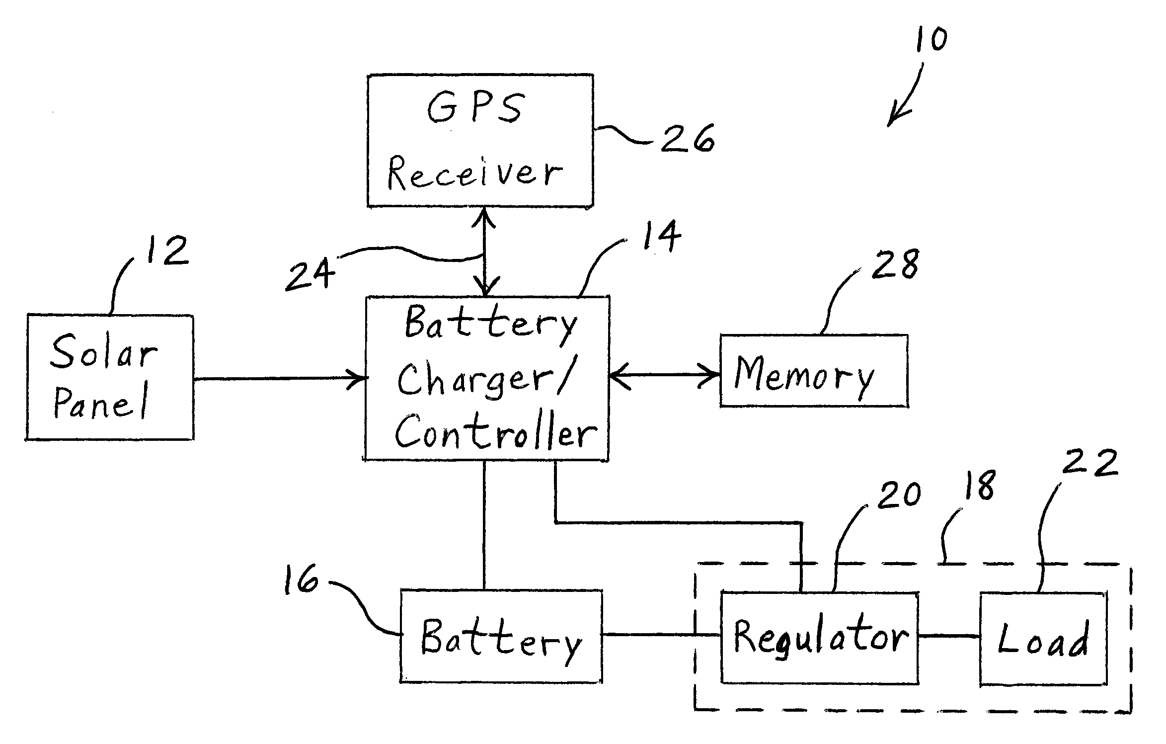
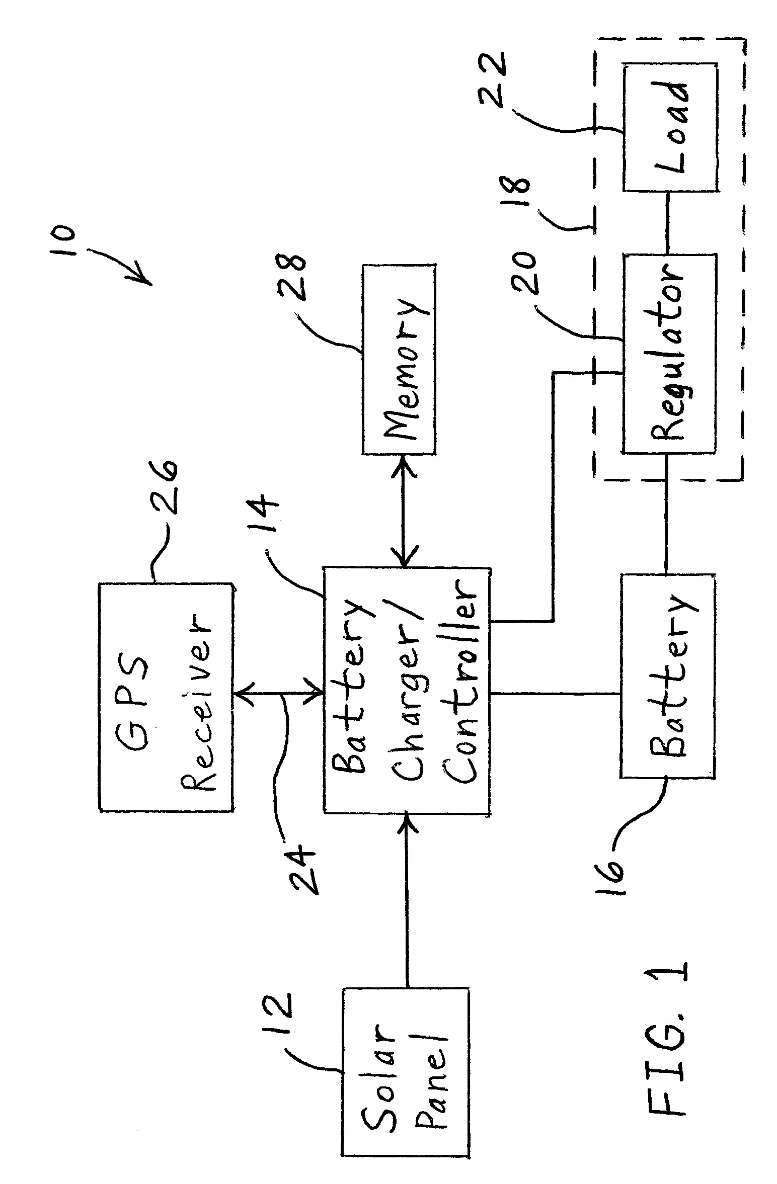
[0020]Referring to FIG. 1, there is shown a block diagram of one embodiment of a solar powered system 10 of the present invention including a solar panel 12, a battery charger / controller 14, and a battery 16 connected to an appliance 18. Appliance 18 may be in the form of a street light, for example. However, it is within the scope of the invention for appliance 18 to be any low-power electrical device, such as a sensor, electronic device or light source, for instance. Appliance 18 may include a regulator 20 for regulating the level of current drawn by a load 22 of appliance 18.

[0021]Controller 14 may be able to communicate via wires 24 or other signal medium with a locally resident GPS receiver 26. In one embodiment,...


PUM


Abstract

A method of operating an electrical appliance includes coupling a solar collector to the electrical appliance such that the solar collector may provide electrical power to the appliance. A global positioning system receiver is used to determine a location of the solar collector. A level of power that may be sourced by the solar collector is calculated wherein the calculation is dependent upon the location of the solar collector as determined by the global positioning system receiver. The appliance is configured to draw a level of power corresponding to the calculated level of power that may be sourced by the solar collector.

Description

RELATED APPLICATION[0001]The present invention claims priority to U.S. Provisional Patent Application No. 61 / 016,066, entitled “SOLAR SYSTEM AUTOMATIC SIZING AND FAILURE IDENTIFICATION ON LOCATION USING RESIDENT GPS RECEIVER”, filed Dec. 21, 2007, which is incorporated herein by reference.BACKGROUND OF THE INVENTION[0002]1. Field of the Invention[0003]The present invention relates generally to global positioning systems (GPS) and, more particularly, global positioning systems used in conjunction with solar panels and / or street lights.[0004]2. Description of the Related Art[0005]Solar panels, or other forms of solar energy collectors, are used in providing electrical power to street lights and other electrical appliances. The amount of power that the solar panel is able to source is dependent to a large part upon the incident angle of the sun's rays on the solar panel, the amount of the earth's atmosphere through which the sun's rays travel to reach the solar panel, and the length of...

Claims


Application Information

Patent Timeline
Patent Type & Authority Applications(United States)
IPC IPC(8): G01D1/18H01J7/42G06F1/28
CPCG01D4/00G01R31/44H02J7/35Y02B90/244Y02B90/245Y04S20/525Y04S20/327Y04S20/40Y04S20/52Y02B70/346Y02B90/248G01D2204/12G01D2204/14G01D2204/30Y02B70/34Y04S20/30Y02B90/20
Inventor BEARS, JAMESSONNENFELDT, MICHAEL
Owner BEARS JAMES
Learn More