Apparatus and method to control and adjust water consumption by a toilet during refill of the bowl and reservior

a technology for toilets and toilets, applied in the direction of diaphragm valves, engine diaphragms, operating means/releasing devices of valves, etc., can solve the problems of sewage discharge, high construction and maintenance costs of sewage delivery systems and treatment plants, and foregoing traditional toilets wasteful and inefficien

Inactive Publication Date: 2009-07-02
SHALEV EFRAIM
View PDF14 Cites 8 Cited by
  • Summary
  • Abstract
  • Description
  • Claims
  • Application Information

AI Technical Summary

Benefits of technology

[0020]An example embodiment of the present invention may include an apparatus that reduces water consumption in a toilet following the release of water from a reservoir. The apparatus may include a toilet bowl and a reservoir that holds water from a water source. The bowl and reservoir may be connected by a tube or an aqueduct structure. The reservoir may include a fill valve that includes a float that aids in detecting whether water in the reservoir is below a first predetermined water level. The reservoir may also include an overflow tube that passes water to the connection tube, a refill tube positioned in a flow of water between the fill valve and the overflow tube, and a water limiting device in the flow of water between the fill valve and the overflow tube.
[0021]When the water level detection mechanism detects that the water in the reservoir is below a first predetermined water level, then the fill valve passes water into the reservoir and the refill tube. As water flows through the refill tube the water limiting device limits the flow of water flowing through the refill tube to reduce the time difference between when the reservoir reaches the first predetermined water level and when the bowl reaches a second predetermined water level.

Problems solved by technology

The foregoing traditional toilet is wasteful and inefficient since a relatively large quantity of water is used to accomplish each flush.
Furthermore, the flushed water represents a considerable volume of the sewage that must be generated and treated.
Sewage delivery systems and treatment plants are expensive to construct and maintain, and require large amounts of land and have offensive odors.
However, such water reduction systems have been faced with problems when the reservoir size is further reduced.
One such problem is that in many cases for the waste to completely drain from the bowl, it becomes necessary to flush the toilet multiple times. This completely negates those benefits of the “low-flush” toilets, as the total consumption per use rises to 2-3 times the intended consumption rate.
In a typical toilet, the time difference between when the toilet bowl 106 is already at its predetermined level 108 and when the reservoir 102 completely refills results in the wasting of about a liter of water per flush.

Method used


Image

  • Apparatus and method to control and adjust water consumption by a toilet during refill of the bowl and reservior
  • Apparatus and method to control and adjust water consumption by a toilet during refill of the bowl and reservior
  • Apparatus and method to control and adjust water consumption by a toilet during refill of the bowl and reservior

Examples


Embodiment Construction

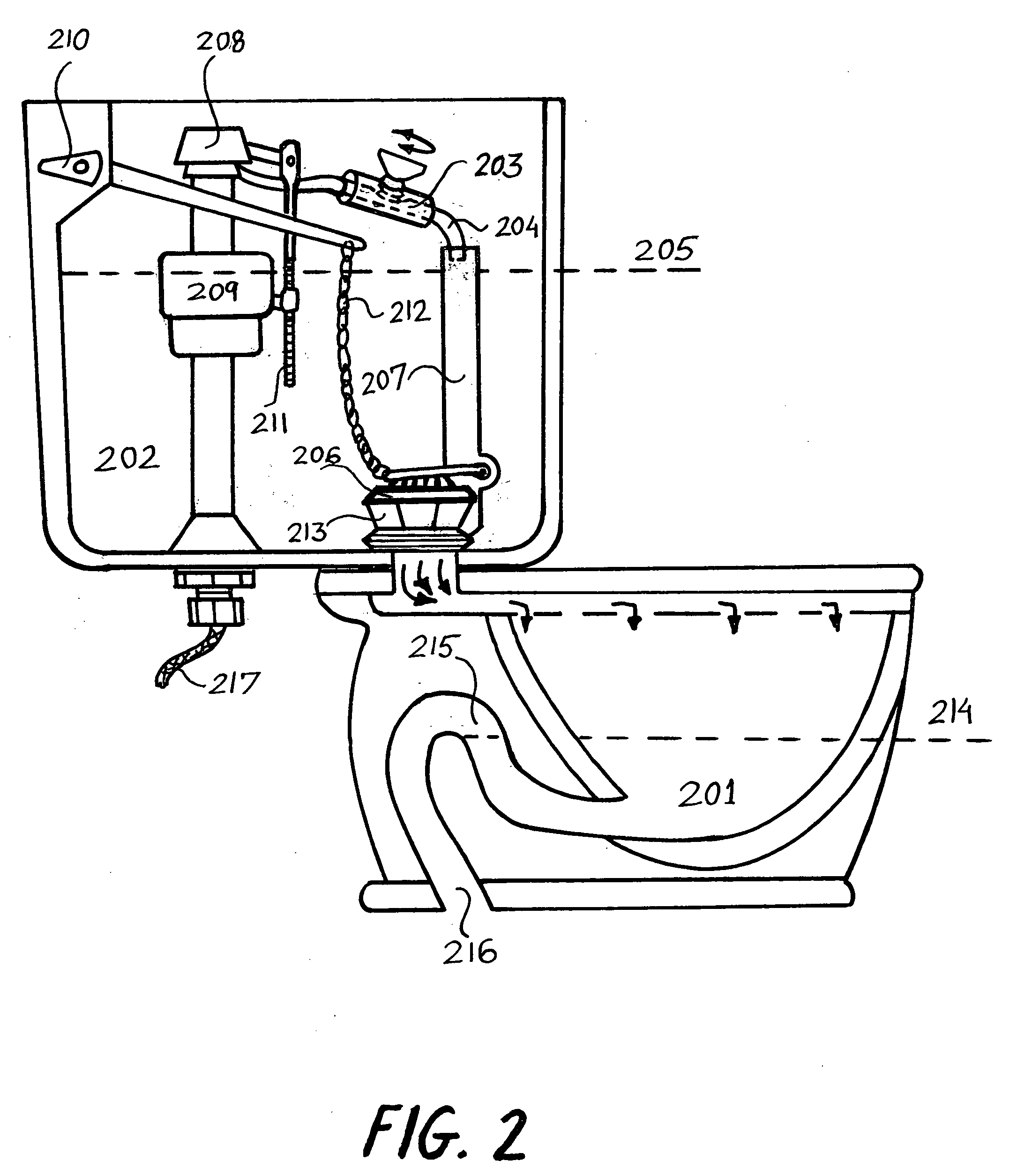
[0032]FIG. 2 illustrates a toilet bowl 201 and reservoir 202 in accordance with an example embodiment of the present invention. The example embodiment employs an adjustable valve 203 as a component of refill tube 204.

[0033]Toilet includes a reservoir 202, designed to hold a first predetermined amount of water, indicated by reservoir water level 205. The water in the reservoir 202 may be held in place by a flush valve 206. The first predetermined amount of water in reservoir 202 may be determined based on the design of the toilet and the necessary amount of water for flushing the toilet bowl 201. The reservoir also includes an overflow tube 207, a fill valve 208, having a float 209, a refill tube 204, having an adjustable valve 203, a flush handle 210, a rod 211, a flapper chain 212, and a flush valve 206, (a “flapper”).

[0034]The overflow tube 204 may be set at a height slightly above the first water level 205. The overflow tube 207 is connected to the connection tube 213. Water ente...


PUM


Abstract

This invention relates generally to an apparatus and a method for plumbing installations and more particularly to a mechanism and use of a mechanism contained within the water tank of a household toilet which improves the water consumption efficiency of the toilet by minimizing the amount of water consumed when refilling the toilet reservoir and bowl. The mechanism can be a constriction or water limiting device, such as an adjustable valve, pinching, squeezing or similar device, positioned in line with a refill tube, and between the fill valve and the overflow tube. By adjusting the flow-rate or maximum volume of water that can pass through the refill tube, the refill time for the toilet bowl and water reservoir can be synchronized, causing the reduction or elimination of water-wasting during refilling time.

Description

CROSS-REFERENCE TO RELATED APPLICATIONS[0001]This application claims priority under 35 U.S.C. §119(e) from co-pending U.S. Provisional Patent Application No. 61 / 009,226 filed Dec. 28, 2007, naming Efraim Shalev as sole inventor, and titled “A SYSTEM AND METHOD FOR CONSERVING WATER WHILE REFILLING TOILET”, which is incorporated by reference herein for all purposes.BACKGROUND OF THE INVENTION[0002]1. Field of the Invention[0003]This invention relates generally to plumbing installations and more particularly to a mechanism contained within the water tank of a household toilet which improves the flushing efficiency of the toilet by minimizing the amount of water consumed when refilling the toilet reservoir and bowl.[0004]2. Description of the Related Art[0005]Conventional toilets have operated by flushing waist into the drain lines using the force generated by gravity rushing water to the toilet bowl. Traditional toilets include a porcelain reservoir, also called a tank, mounted immedia...

Claims


Application Information

Patent Timeline
Patent Type & Authority Applications(United States)
IPC IPC(8): E03D1/00
CPCE03D1/00F16K31/20F16K7/061E03D1/32
Inventor SHALEV, EFRAIM
Owner SHALEV EFRAIM
Why Eureka
Try Eureka