
Valve With Built-In Sensor

a sensor and valve technology, applied in the field of valves, can solve problems such as health problems, significant structural damage, and continued destruction

Inactive Publication Date: 2009-07-02
FIMA GIOVANNI
View PDF30 Cites 47 Cited by
  • Summary
  • Abstract
  • Description
  • Claims
  • Application Information

AI Technical Summary

Benefits of technology

[0015]It is also contemplated that a second existing valve within the same fluid distribution system could be replaced with a second valve having a second sensor, similar to the first valve described above. Furthermore, a plurality of existing valves could be retrofitted, such as throughout a building to provide a plurality of valves that continuously monitor the properties of the fluid and can shut-off flow and communicate an alert to reduce the risk of water leaks. In addition, the new valve can optionally be placed to provide a drainage system to the existing distribution system to help prevent water leaks and / or pipe bursts. For example, a two-way and a three-way valve could be used in combination to provide a drain for fluid in the system by rotating the valves when a threshold temperature is reached.
[0017]The sensor within the valve provides a signal that represents a specific property of the fluid including for example, a flow rate, temperature, and pressure. Any type of commercially available sensor is contemplated including those discussed above. In one aspect, a device remotely monitors the sensor signal. As used herein, “remotely” is defined as a distance of at least one foot, preferably ten feet, and more preferably 100 feet from the sensor. In addition, it is contemplated that the signal could be communicated with a remote computer and monitored via a computer interface. Thus, the computer could monitor a plurality of sensors and thus provide a central monitoring location. This can be advantageous in a building having multiple units and floors, such as a commercial high-rise. In this manner, a building manager can quickly be apprised of the status of the fluid system within the building and be immediately alerted to any problems.

Problems solved by technology

The second is that once a leak has begun, it often continues with devastating results.
Fluid leaks, and particularly water leaks, can cause a significant amount of structural damage and health issues from resulting mold.
This stretch of plumbing is typically the weakest link in a water system and is prone to malfunction and rupture.
One problem with these systems is that they typically have many parts and require installation by a trained technician.
In addition, such sensors generally can only be monitored locally and often require installation of extra components.
Further, because fluid distribution systems are often complex and inaccessible (e.g., located underground, behind walls, etc.), multipart and complex systems become more difficult to install, replace and upgrade.
However, while sensors are simple to install during a new construction of a building, retrofitting an existing system is typically complex and cumbersome, especially as fluid systems are often inaccessible or otherwise difficult to reach, and often require extensive wiring.
In addition, as the number of units and floors that need to be retrofitted increase, the cost often becomes prohibitive.

Method used


Image

  • Valve With Built-In Sensor
  • Valve With Built-In Sensor
  • Valve With Built-In Sensor

Examples


Embodiment Construction

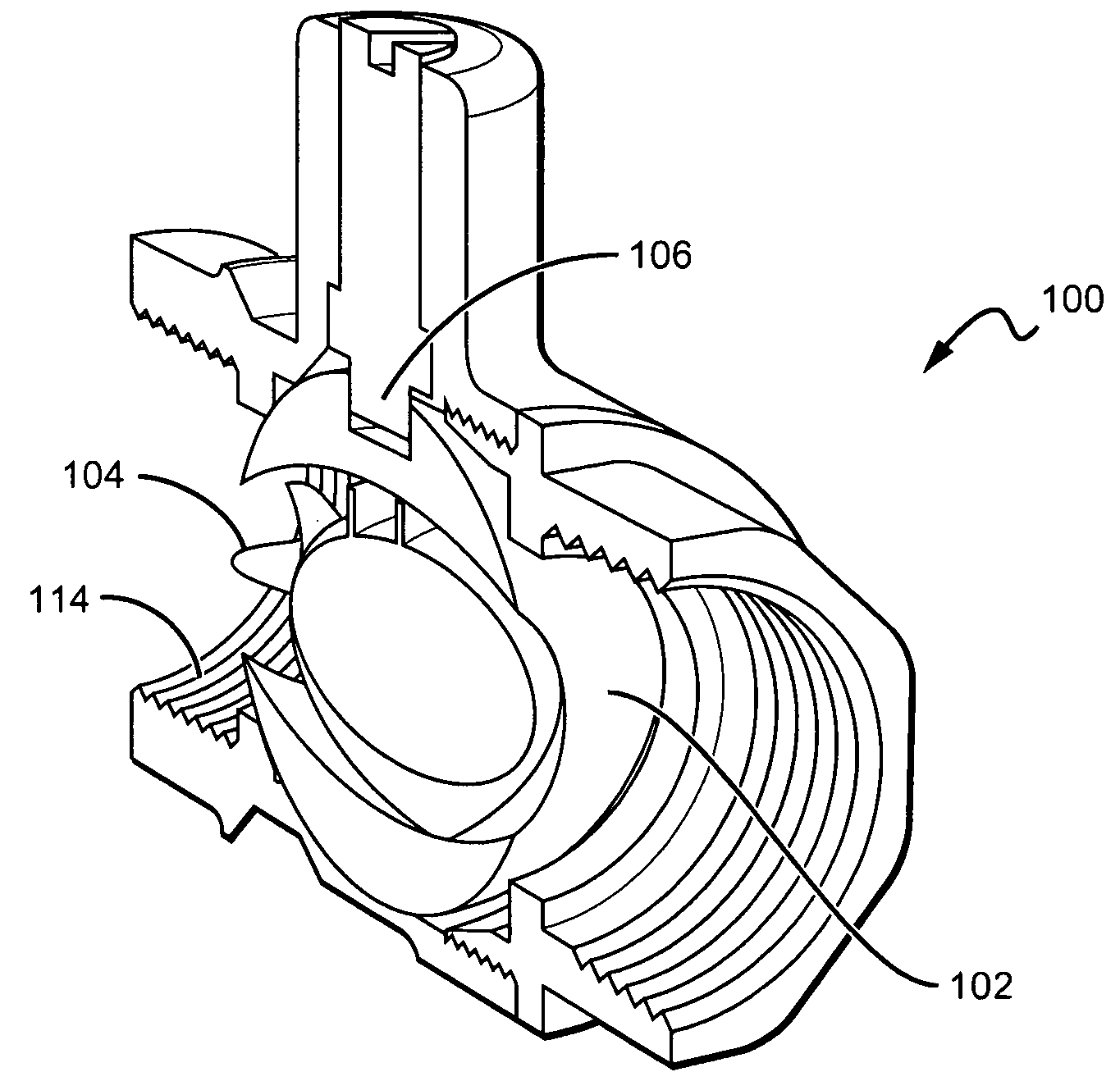
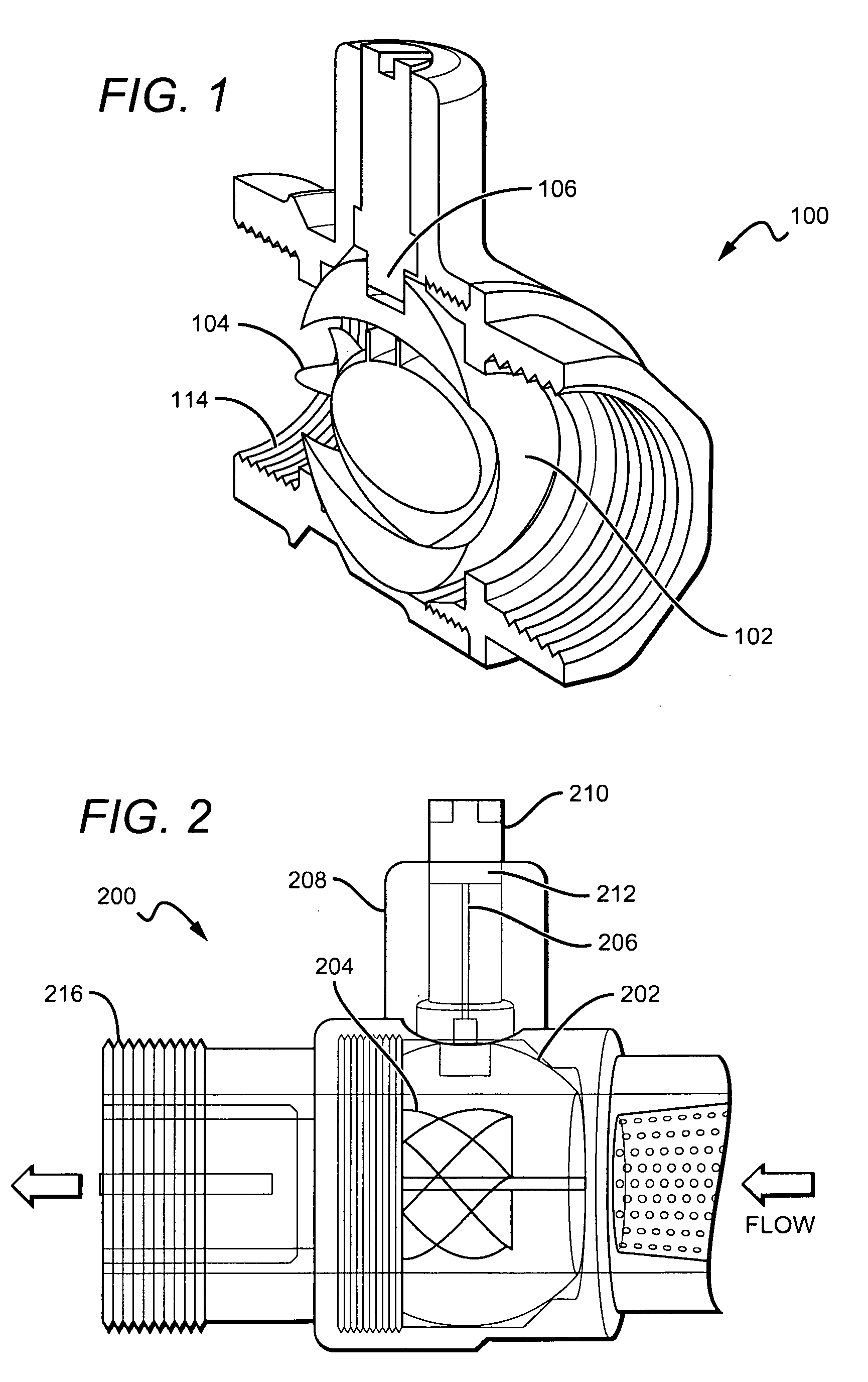
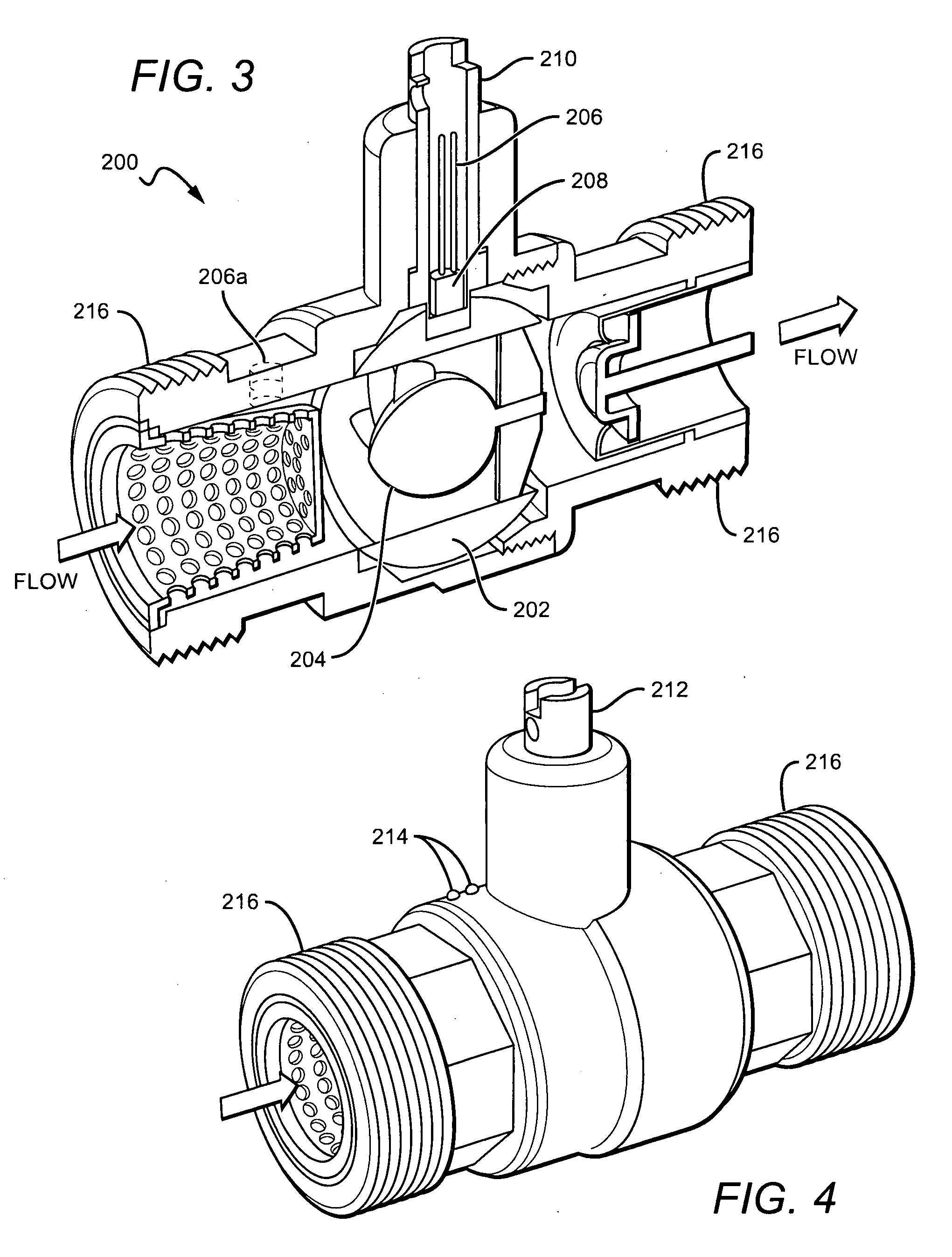
[0032]In FIG. 1, a valve 100 is shown comprising a control ball 102 with a sensor 106 disposed within the passageway 114 of the control ball 102.

[0033]Valve 100 is a ball valve that defines a fluid passageway 114. While a ball-valve is shown, it is contemplated that the valve can include any commercially available type of valve into which a built-in sensor can be disposed. Control ball can be composed of any suitable material including for example, metals such as stainless steel, chrome, and brass, plastics, ceramics, and any combination thereof. Although fluid passageway 114 has a one-way design, two-way, three-way, and other passageway designs are also contemplated. In addition, the passageways could be designed to direct flow in various directions including a direction normal to the fluid flow, such as through an “L”-shaped passageway.

[0034]Sensor 106 is a flow sensor comprising an electromagnetic sensor that operates in conjunction with turbine 104 having a magnet. Preferably, t...


PUM


Abstract

A valve is disclosed that has a control ball. The control ball has a passageway within which a sensor is disposed. The sensor measures a characteristic of the fluid passing through the control ball. The control ball can be controlled either manually or with an electronic actuator. A method is disclosed of retrofitting an existing fluid distribution system by replacing a valve that lacks sensing capabilities with a new valve having a sensor. The sensor measures the flow, temperature, or pressure of the fluid, and provides a signal that can be remotely monitored and corresponds to the measured characteristic.

Description

[0001]This application claims priority to U.S. provisional application with the Ser. No. 61 / 009,473, which was filed on Dec. 28, 2007. This and all other extrinsic materials discussed herein are incorporated by reference in their entirety. Where a definition or use of a term in an incorporated reference is inconsistent or contrary to the definition of that term provided herein, the definition of that term provided herein applies and the definition of that term in the reference does not apply.FIELD OF THE INVENTION[0002]The field of the invention is valves.BACKGROUND[0003]There are two primary reasons for fluid leaks in a water system. The first is that plumbing is typically an open system. The second is that once a leak has begun, it often continues with devastating results. Fluid leaks, and particularly water leaks, can cause a significant amount of structural damage and health issues from resulting mold. In a major study of water leaks by FluidMaster™, the results indicated that 8...

Claims


Application Information

Patent Timeline
IPC IPC(8): F16K37/00
CPCF16K47/045F16K5/0605F16K37/005G01F1/00Y10T137/0486Y10T137/8158Y10T137/9029
Inventor FIMA, GIOVANNI
Owner FIMA GIOVANNI
Learn More