
Fluid Flow Labyrinth

a technology of flow labyrinth and labyrinth, which is applied in the direction of fluid dynamics, fluid heaters, light and heating apparatus, etc., can solve the problem of a “comparatively low” sensitivity of the outflow of water from the emitter to the change of the inlet water, and achieve the effect of reducing pressur

Active Publication Date: 2009-07-02
NETAFIM LTD
View PDF6 Cites 47 Cited by
  • Summary
  • Abstract
  • Description
  • Claims
  • Application Information

AI Technical Summary

Benefits of technology

[0009]An aspect of some embodiments of the invention relates to providing a labyrinth channel that comprises a new configuration of baffles for reducing pressure in a fluid that flows through the channel and / or the fluid flow rate through the channel.

Problems solved by technology

The patent notes that the increased pressure reduction functionality results in a “comparatively low” sensitivity of outflow of water from an emitter to changes in inlet water pressure to the emitter.

Method used


Image

  • Fluid Flow Labyrinth
  • Fluid Flow Labyrinth
  • Fluid Flow Labyrinth

Examples


Embodiment Construction

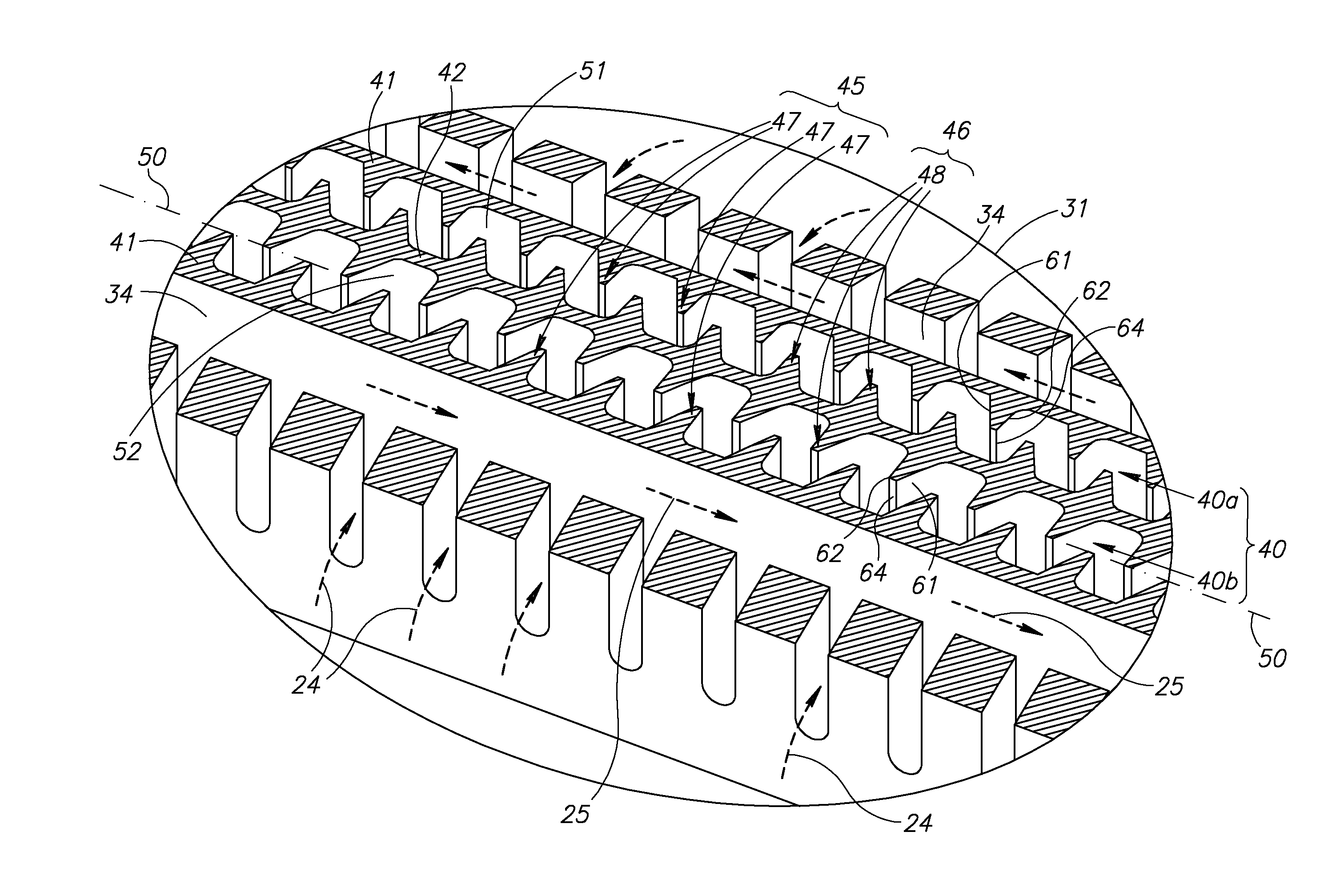
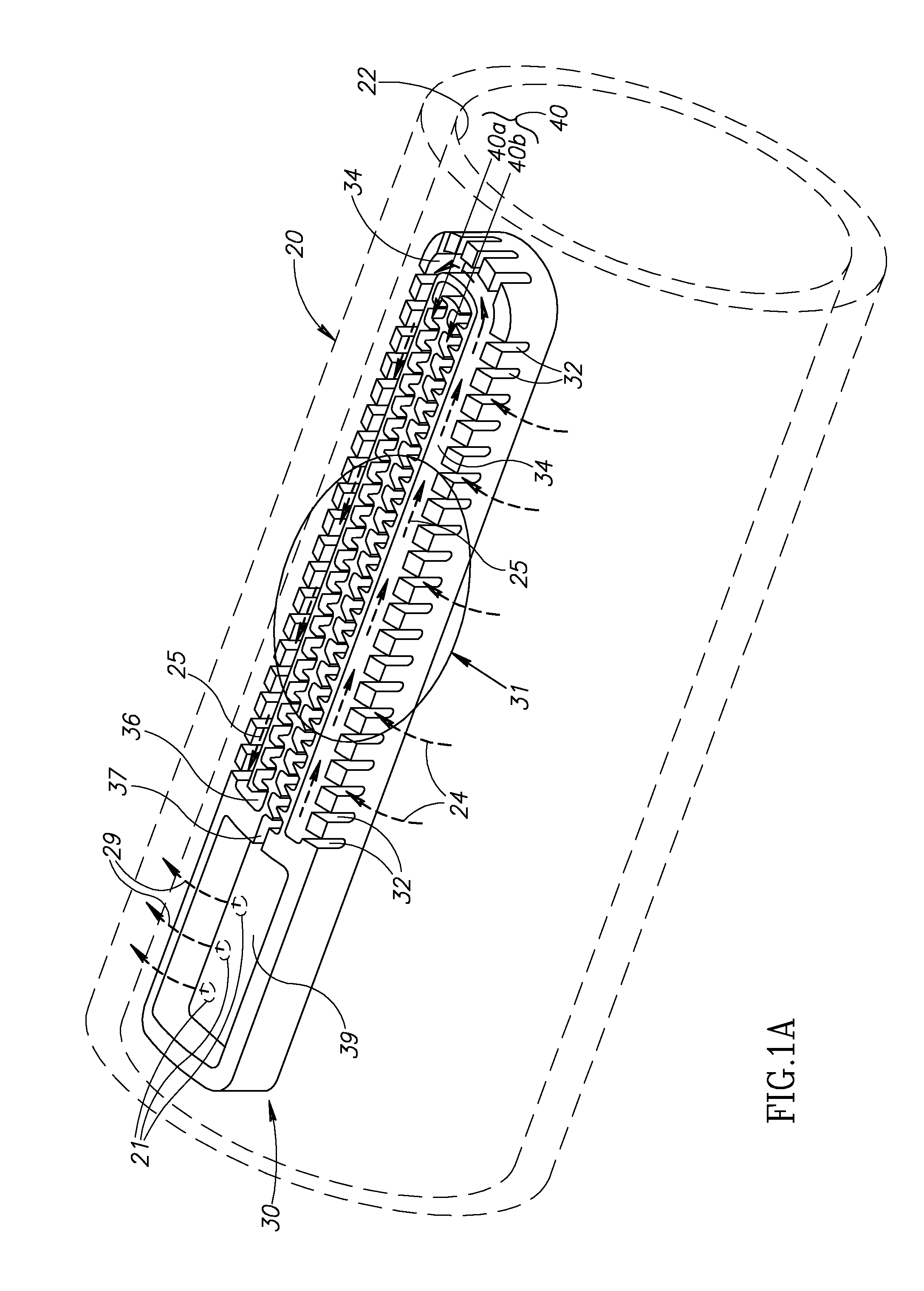
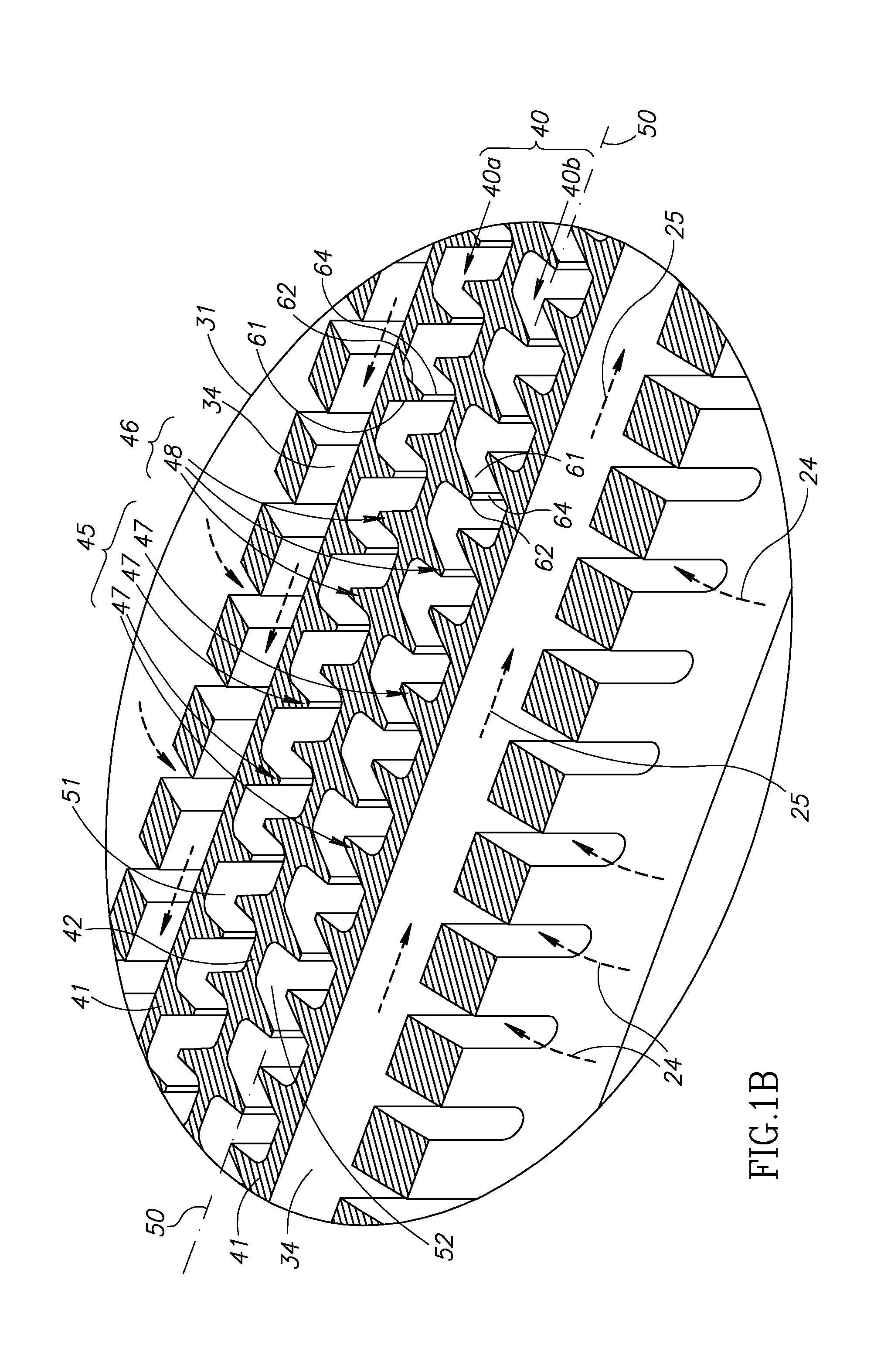
[0032]FIG. 1A schematically shows a perspective view of a portion of an irrigation pipe 20 having an internally mounted emitter 30 comprising a labyrinth channel 40, in accordance with an embodiment of the invention. An enlarged view of a portion of emitter 30 is shown in FIG. 1B. The enlarged portion of emitter 30 that is shown in FIG. 1B is indicated by an ellipse 31 in FIG. 1A. FIG. 1C schematically shows a plan view of emitter 30 and a portion, indicated by ellipse 33, of emitter 30 in FIG. 1C is shown greatly enlarged in FIG. 1D. Emitter 30 is optionally formed from a plastic and is bonded to an inside surface 22 of irrigation pipe 20 using any of various methods, such as thermal or ultrasound welding, known in the art. After bonding to surface 22, the portion of the surface to which it is bonded optionally forms a wall, or “roof” of the emitter that delimits labyrinth channel 40. In FIGS. 1B-1D surfaces of emitter 30 that are bonded to inside surface 22 of pipe 20 are shown sh...


PUM


Abstract

A labyrinth channel for reducing pressure and / or flow rate in a liquid flowing in the channel, the labyrinth channel having a bottom surface and first and second opposing walls and comprising: a first array of spaced apart first baffle teeth that have non-parallel upstream and downstream faces and extend from the first wall towards the second wall to terminate in an end; and a second array of spaced apart second baffle teeth that have non-parallel upstream and downstream faces and extend from the second wall towards the first wall to terminate in an end; wherein baffle teeth in different arrays have a substantially same shape and upstream faces of closest baffle teeth in different arrays are different and / or downstream faces of closest baffle teeth in different arrays are different.

Description

[0001]The invention relates to fluid flow control labyrinths and in particular labyrinths that are used to restrict water flow from emitters used in drip irrigation.BACKGROUND OF THE INVENTION[0002]Irrigation systems that deliver water, often containing plant nutrients, pesticides and / or medications, to plants via networks of irrigation pipes are very well known. In many such irrigation networks, water from an irrigation pipe is delivered to the plants by “emitters” or “drippers”, hereinafter generically referred to as emitters, which are connected to or installed along the length of the pipe. Each emitter comprises at least one inlet or an array of inlets through which water flowing in the pipe enters the emitter and an outlet through which water that enters the emitter exits the emitter. The emitter diverts a relatively small portion of water flowing in the pipe and discharges the diverted water to irrigate plants in a neighborhood of the location of the emitter.[0003]Generally, t...

Claims


Application Information

Patent Timeline
IPC IPC(8): F16L55/027
CPCA01G25/023
Inventor SOCOLSKY, ESTEBAN ARIEL
Owner NETAFIM LTD
Features
  • Generate Ideas
  • Intellectual Property
  • Life Sciences
  • Materials
  • Tech Scout
  • Unparalleled Data Quality
  • Higher Quality Content
  • 60% Fewer Hallucinations
Learn More