Robotic locomotion method and mobile robot

a robot and locomotion technology, applied in the direction of steering control, non-vehicle mounted steering control, brake system, etc., can solve the problems of complex, expensive, complicated, and other impractical solutions, and achieve the effect of easy displacement, easy detection of surface contamination, and easy measurement of surface thickness

Inactive Publication Date: 2009-07-02
WAIBEL MARKUS +1
View PDF25 Cites 58 Cited by
  • Summary
  • Abstract
  • Description
  • Claims
  • Application Information

AI Technical Summary

Benefits of technology

[0025]According to one aspect, the invention also relates to an improved method and system for cleaning, treating or investigating surfaces. The use of two devices coupled by an attractive force allows for small, light and agile devices that can be easily displaced from one surface to another. By using two devices on opposing sides, the invention also allows other advantages including simultaneous clea

Problems solved by technology

However, many tasks which could potentially be addressed by robotic systems, do not meet these conditions.
Several systems known in the related art have addressed this problem, but opposed to our invention, the suggested solutions are not suitable for implementation in a small inexpensive robotic device due to high energy requirements, low flexibility or other constraints detailed below.
A common problem with many related art solutions is that they rely on ad hoc support elements, like ropes, rails and scaffolds, that lead to complicated, expensive, or otherwise impractical solutions.
Another common l

Method used


Image

  • Robotic locomotion method and mobile robot
  • Robotic locomotion method and mobile robot
  • Robotic locomotion method and mobile robot

Examples


Embodiment Construction

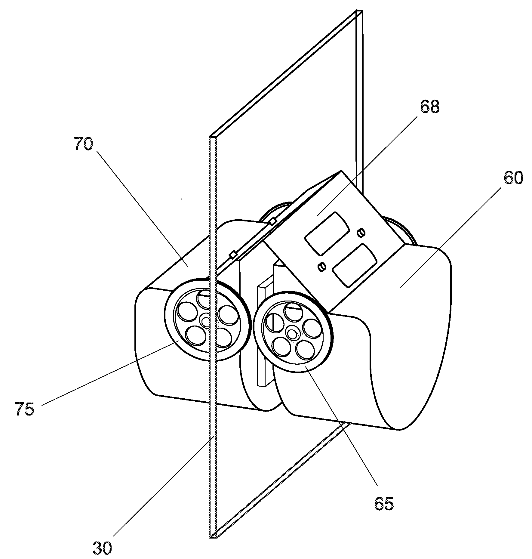
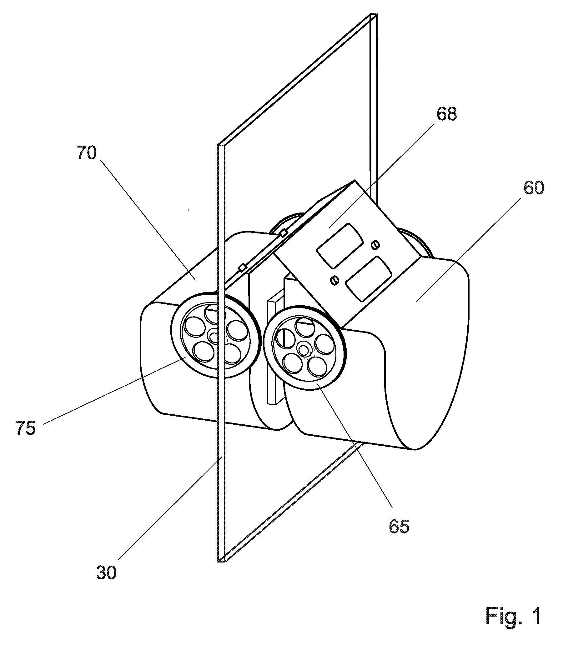
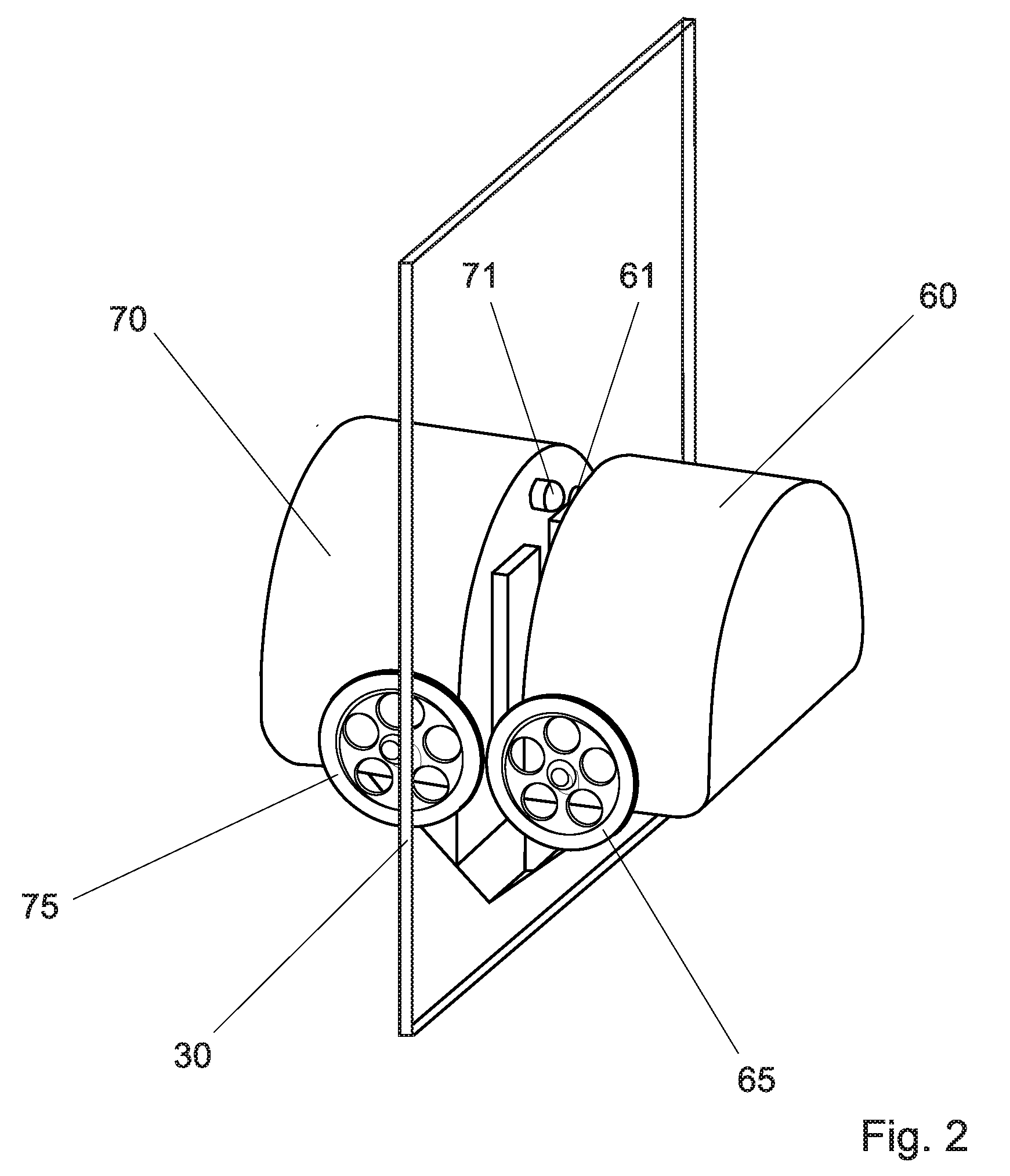
[0034]The present invention generally relates to locomotion of two or more devices 60, 70 on a surface 30, specifically to those cases where at least one device is a mobile robot. Devices on opposing sides of the surface are coupled by an attractive force, which helps generate enough friction between said devices and the surface to allow devices to move across the surface.

[0035]In one preferred embodiment of this invention the devices used are two autonomous robots located on opposing sides of a window glass or any other surface (FIGS. 1-6). The invention includes other embodiments, however, in which one autonomous robot is located on a first side of a surface, and a passive mobile device is located on the opposite side of the surface, and an attractive force generated by either one or the other or both devices between the devices generates friction between the devices and the surface, allowing said devices to move on the surface. Said force between the devices may also be used to m...


PUM


Abstract

A method for the locomotion of devices on opposite sides of a surface, one or more of which are mobile robots. Devices on opposing sides of the surface are coupled by an attractive force, which helps generate enough friction between said devices and the surface to allow devices to move across the surface.

Description

FIELD OF THE INVENTION[0001]This invention relates to locomotion of devices on a surface, specifically to those cases where at least one device is a mobile robot. Embodiments of the present invention include attraction systems, in which a mobile robot is attracted, by electrostatic or electromagnetic force, to a mobile element on the opposite side of the surface.[0002]In this context, a surface may be any thin, two-sided material such as a flat or rigid structure like a board, pane, panel, window, or wall; a non-flat structure like the hull of a ship, boat, plane, or terrestrial vehicle; or a non-rigid structure like a sail, tent or curtain. Importantly, the present invention allows the operation of a mobile robot on non-horizontal surfaces, on which conventional robots would have no grip. The system and method of the invention allow operating a robot on vertical or even overhanging surfaces inaccessible to conventional systems.RELATED ART[0003]The operation of most terrestrial robo...

Claims


Application Information

Patent Timeline
IPC IPC(8): B62D57/024B63B9/00B08B1/00B63B59/10
CPCB08B1/008B63B59/10B62D57/024
Inventor WAIBEL, MARKUSDUERR, PETER
Owner WAIBEL MARKUS
Why Eureka
Try Eureka