Perpendicular magnetic medium with shields between tracks

Inactive Publication Date: 2009-07-02
HEADWAY TECH INC
View PDF14 Cites 16 Cited by
  • Summary
  • Abstract
  • Description
  • Claims
  • Application Information

AI Technical Summary

Benefits of technology

[0016]Another object of at least one embodiment of the present invention has been that said increase in track density be achieved without affecting the adjacent track erasure field or increasing the level of read-back noise.
[0020]First, during writing the shield absorbs leakage flux from the write head and channels the side flux directly to the soft underlayer to help reduce erasure of adjacent tracks. Such shielding mechanism helps confine the write field to the current track.

Problems solved by technology

However, it is more expensive to use than substrate patterning.
However, all existing methods to produce a patterned magnetic medium result in physically defined magnetic data tracks that are separated from adjacent tracks by air spacing or by spacing filled with non-magnetic materials.
This smaller size inevitably degrades the down-track gradient of the write head due to the reduced magnetic volume which, in turn, limits the highest down-track bit density achievable.
It is foreseeable that the trade-off between down-track data density and cross-track data density will reach a point where further increases in track density will no longer lead to an effective increase of data area density, due to the density loss in the down-track direction.

Method used


Image

  • Perpendicular magnetic medium with shields between tracks
  • Perpendicular magnetic medium with shields between tracks
  • Perpendicular magnetic medium with shields between tracks

Examples


Embodiment Construction

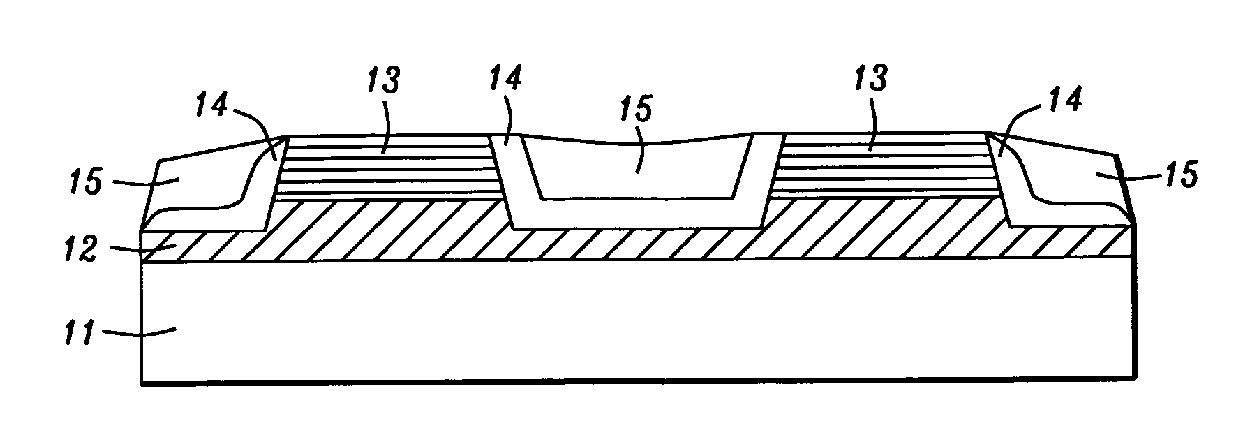
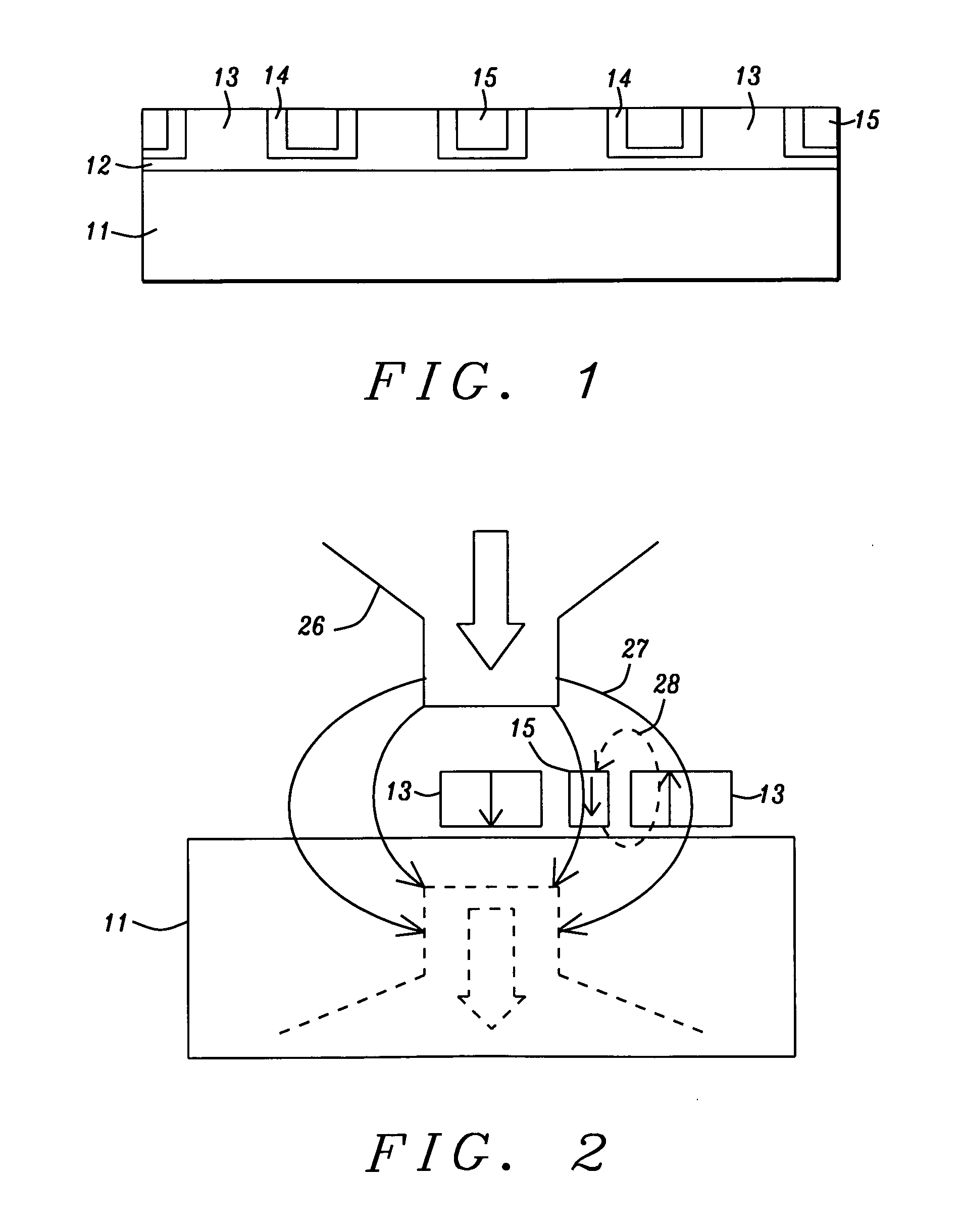
[0028]FIG. 1 is an illustrative overview of the invention. Shown there is an example of a between-track soft magnetic shielding wall in a patterned track magnetic medium. After patterning of the magnetic recording layers into isolated data tracks 13, non-magnetic spacer layer 14 is deposited into the trenches that separate the adjacent data tracks. Afterwards, soft magnetic material is deposited into the trenches as well over 14 thereby fully filling the trench area. This soft magnetic line that is conformal with the patterned track runs between adjacent tracks and acts as magnetic flux shielding wall 15 within the patterned medium.

[0029]Underlayer 11 serves as the substrate on which the thin film layers of the medium are to be deposited. Etched layer 12 is where etching to form the patterned track was terminated. Patterned layer 13 is the layer that is being patterned into physical tracks. Underlayer 11 supports the non-magnetic layer 12 while layer 13 includes all the magnetic and...


PUM

PropertyMeasurementUnit
Angleaaaaaaaaaa
Angleaaaaaaaaaa
Angleaaaaaaaaaa

Abstract

A track shield structure is disclosed that enables higher track density to be achieved in a patterned track medium without increasing adjacent track erasure and side reading. This is accomplished by placing a soft magnetic shielding structure in the space that is present between the tracks in the patterned medium. A process for manufacturing the added shielding structure is also described.

Description

FIELD OF THE INVENTION[0001]The invention relates to the general field of magnetic recording with particular reference to shielding adjacent tracks from one another.BACKGROUND OF THE INVENTION[0002]Perpendicular recording at high area density requires increases of track density due to the down-track bit length approaching its smallest size achievable by state-of-the-art write head field down-track gradient. This increase of track-density demands a sharper cross-track field gradient of the writer field as well as better stability and less noise of the magnetic data track in the cross-track direction. Prior study [1] suggests that a patterned track medium, where magnetic data tracks are physically separated from each other by a non-magnetic trench or by a spacer, not only reduces reader noise pickup from erasure bands between the tracks, due to the well defined track width, but also increases on-track data stability against leakage field erasure while the writer is writing on adjacent...

Claims


Application Information

Patent Timeline
IPC IPC(8): C23C14/32G11B5/33G11B5/706
CPCB82Y10/00C23C14/225C23C16/45555G11B5/746G11B5/82G11B5/855G11B5/743
Inventor ZHOU, YUCHENGUAN, LIJIEZHANG, KUNLIANG
Owner HEADWAY TECH INC
Why Eureka
Try Eureka