
Counter flow type of cooling tower generating low grade of noise

a cooling tower and flow type technology, applied in the direction of carburetor air, lighting and heating equipment, separation processes, etc., can solve the problems of increasing noise and not having cooling effect, and achieve the effect of preventing moisture and low nois

Active Publication Date: 2009-07-02
HOOSAN
View PDF9 Cites 14 Cited by
  • Summary
  • Abstract
  • Description
  • Claims
  • Application Information

AI Technical Summary

Benefits of technology

[0011]This invention is provided to resolve the problems of the prior counter flow type of cooling tower. Specifically, a noise generation restraining portion is provided between the filler and the collection tank, thereby allowing the coolant passing the filler to flow along the noise generation restraining portion and preventing the coolant from dropping. Thus, the noise caused when the coolant drops can be fundamentally shut out, the coolant can be prevented from being scattered to the exterior while dropping, air resistance caused by the noise generation restraining portion can be minimized, and the cooling effect can be enhanced because the noise generation restraining portion first cools the coolant.

Problems solved by technology

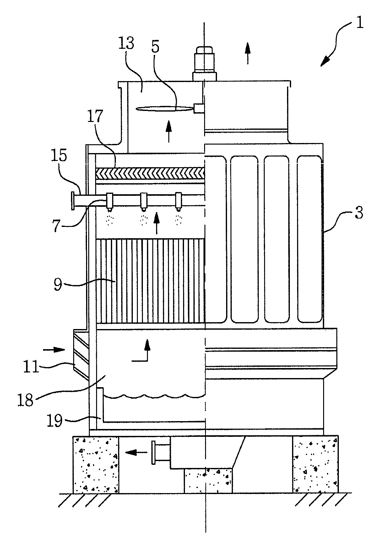
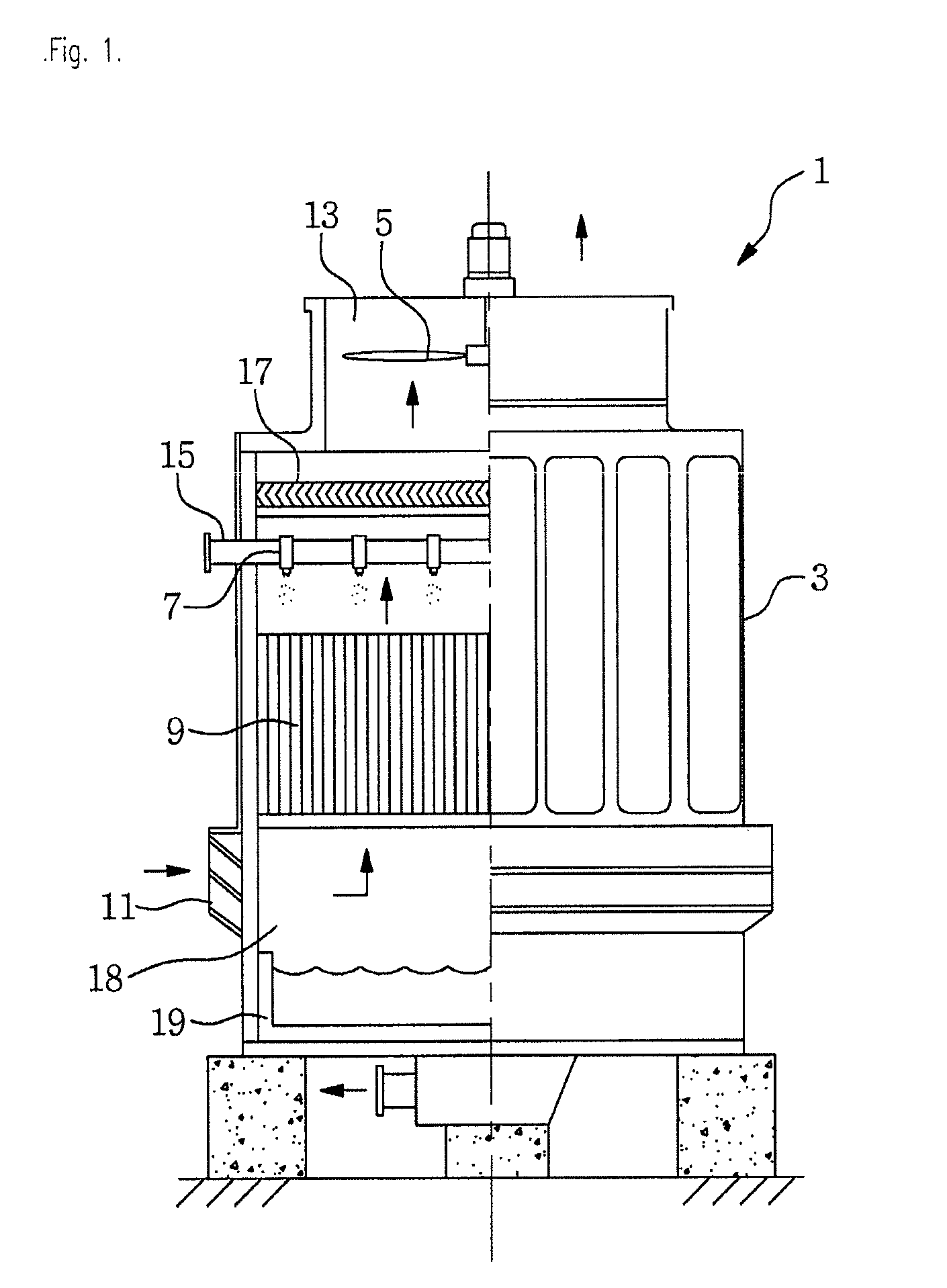
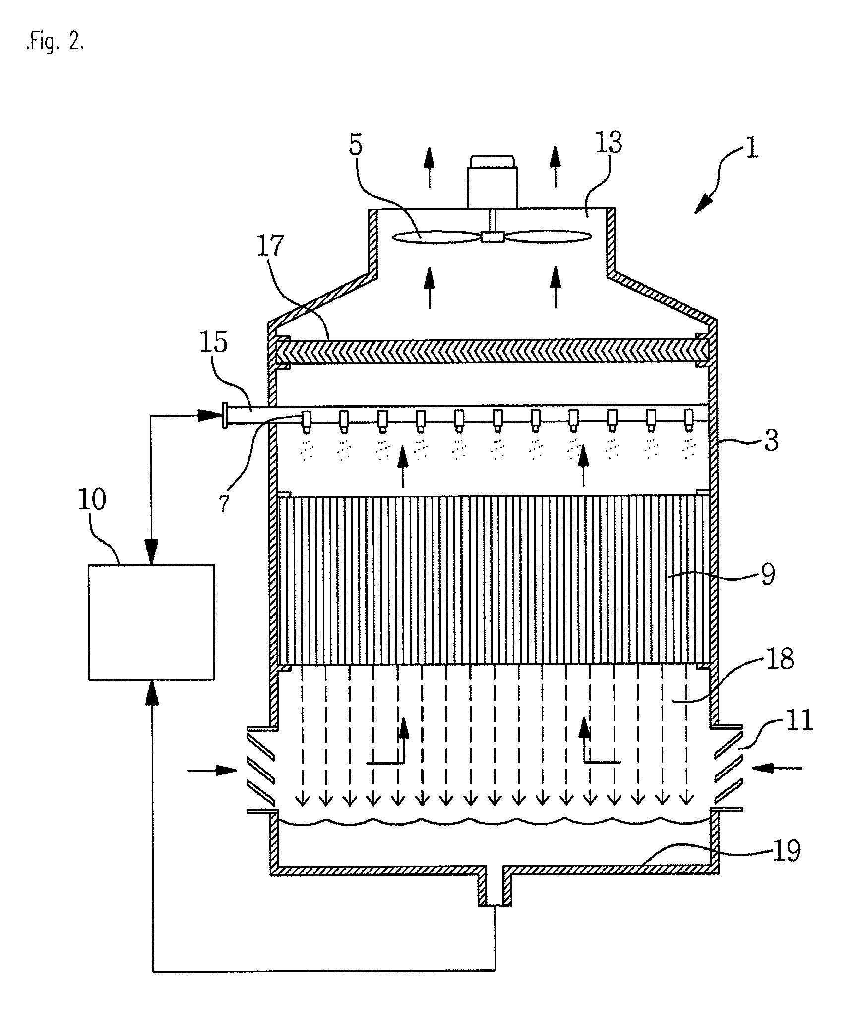
Since the filler (9) is spaced from and installed above the collection tank (19), the prior counter flow type of cooling tower (1) had a problem that while the coolant drops through the space portion (18), it directly contacts air and is scattered with air to the exterior and in particular, that water drops of the coolant passing through the space portion (18) increase noise and the cooling effect is not great because the coolant is cooled only by the filler (9).

Method used


Image

  • Counter flow type of cooling tower generating low grade of noise
  • Counter flow type of cooling tower generating low grade of noise
  • Counter flow type of cooling tower generating low grade of noise

Examples


Embodiment Construction

[0036]Preferred embodiments of the counter flow type of cooling tower generating low grade of noise according to this invention are set forth below with reference to the accompanying drawings. The constitutions in this invention that correspond to the constitutions in the prior art use the same names and an explanation thereof are omitted.

[0037]FIG. 3 is a schematic sectional view of the counter flow type of cooling tower generating low grade of noise according to a preferred embodiment of the invention. FIG. 4 is a schematic perspective view of the noise generation restraining portion comprised in the counter flow type of cooling tower generating low grade of noise according to a first preferred embodiment of the invention. FIG. 5 is a schematic perspective view of the noise generation restraining unit constituting the noise generation restraining portion illustrated in FIG. 4. FIG. 6 is a sectional view taken along the line A-A of FIG. 5. FIG. 7 is a sectional view taken along the...


PUM

PropertyMeasurementUnit
widthaaaaaaaaaa
temperatureaaaaaaaaaa
pressureaaaaaaaaaa

Abstract

This invention relates to a counter flow type of cooling tower generating low grade of noise, which includes: a body wherein an external air inhalation hole is formed in the lower portion and a discharge hole is formed in the upper portion; a fan that is provided in the body and absorbs external air into the body through an inhalation hole and discharges the external air to the discharge hole; an spraying nozzle that sprays coolant; an eliminator that is provided above the spraying nozzle and prevents air and water from scattering; a filler that is provided below the spraying nozzle; and a collection tank collecting the coolant that passes the filler and drops, wherein a space portion is formed between the filler and the collection tank, and the space portion formed between the filler and the collection tank further includes a noise generation restraining portion consisting of at least one noise generation restraining unit. According to the invention, the noise that occurs when the coolant directly drops into the collection tank is reduced, the scattering of the coolant by incoming air may be prevented, the loss of pressure by the noise generation restraining portion is minimized, the amount of lost coolant and air may be reduced, and the cooling efficiency increases because the noise generation restraining portion maximizes the cooling effect.

Description

FIELD OF THE INVENTION AND DESCRIPTION OF RELATED ART [0001]This invention relates to a counter flow type of cooling tower, and particularly to a counter flow type of cooling tower generating low grade of noise, which allows the coolant flowing down from a filler to flow down by a first inclination plate and a support member of a noise generation restraining portion and come into a collection tank, thereby preventing the generation of noise caused when the coolant drops, preventing the coolant from scattering while dropping, and reducing the amount of the coolant that is included in external air and escapes to the exterior; and which is easy to produce and can minimize the decline in pressure caused by the noise generation restraining portion.[0002]Generally, a cooling tower is an apparatus for lowering the temperature of heated coolant, which was used for an indoor unit of a centralized air conditioning system, i.e., an indoor air conditioner. It is divided into two types: an open ...

Claims


Application Information

Patent Timeline
Patent Type & Authority Applications(United States)
IPC IPC(8): F28C3/06
CPCF28C1/10F28C1/02Y10S261/11Y02B30/70
Inventor LEE, HOO-KUNJANG, KIL-NAMKIM, YONG-BEOM
Owner HOOSAN
Learn More