Control device for rotating electric machine

a technology of control device and electric machine, which is applied in the direction of machines/engines, mechanical equipment, and electric commutators, etc., can solve the problems of difficult to effectively eliminate difficult to correctly reduce electromagnetic force, and difficult to effectively reduce etc., to achieve the effect of reducing electromagnetic force components causing nois

Active Publication Date: 2016-11-24
DENSO CORP
View PDF2 Cites 6 Cited by
  • Summary
  • Abstract
  • Description
  • Claims
  • Application Information

AI Technical Summary

Benefits of technology

[0010]It is therefore desired to provide a control device for rotating electric machines capable of effectively reducing electromagnetic force which causes noise such as magnetic noise if loads of the rotating electric machine change.
[0014]The operation section calculates the amplitude and phase of the harmonic currents to be superimposed over the fundamental current on the basis of the conditions relating to the variable load of the rotating electric machine. Accordingly, if the load of the rotating electric machine varies, the harmonic currents corresponding correctly to the varied load of the rotating electric machine are superimposed over the fundamental current. It is therefore possible for the control device to effectively reduce electromagnetic force components which cause noise.
[0020]Accordingly, even if the conditions of the fundamental current are changed due to the variation of the load of the rotating electric machine, the harmonic current calculation section superimposes the harmonic currents corresponding correctly to the change of the load of the rotating electric machine over the fundamental current. Even if the change of the conditions of the fundamental current occurs, it is possible to reduce electromagnetic force components causing noise.
[0024]According to the present invention, the correlation relationship between the conditions of the instruction values affecting a magnitude of load of the rotating electric machine and the amplitude and phase of the harmonic currents to be superimposed over the fundamental current have been determined. The harmonic current calculation section calculates the amplitude and phase of the harmonic currents to be superimposed over the fundamental current on the basis of the correlation relationship and the conditions of the instruction values. That is, the harmonic current calculation section calculates the harmonic currents corresponding to the conditions of the instruction values which affect a magnitude of the load of the rotating electric machine. Accordingly, even if the load of the rotating electric machine varies due to the change of the instruction values, the harmonic current calculation section superimposes the harmonic currents corresponding correctly to the change of the load of the rotating electric machine over the fundamental current. Even if the conditions of the instruction values affecting the magnitude of load of the rotating electric machine are changed, it is possible to reduce electromagnetic force components causing noise.

Problems solved by technology

When the load of the motor varies, there is a possible risk that it is difficult to correctly reduce electromagnetic force which causes noise if the harmonic current having the same condition before the change of the load of the rotating electric machine is superimposed over the fundamental current.
When the conditions of the fundamental current are changed, there is a risk that it is difficult to effectively eliminate electromagnetic force components causing noise even if the harmonic currents before the change of the conditions of the fundamental current are superimposed over the fundamental current.
There is a risk that it is difficult to effectively reduce electromagnetic force causing noise even if the harmonic currents before the change of the instruction values for the rotating electric machine are superimposed over the fundamental current.

Method used


Image

  • Control device for rotating electric machine
  • Control device for rotating electric machine
  • Control device for rotating electric machine

Examples


first exemplary embodiment

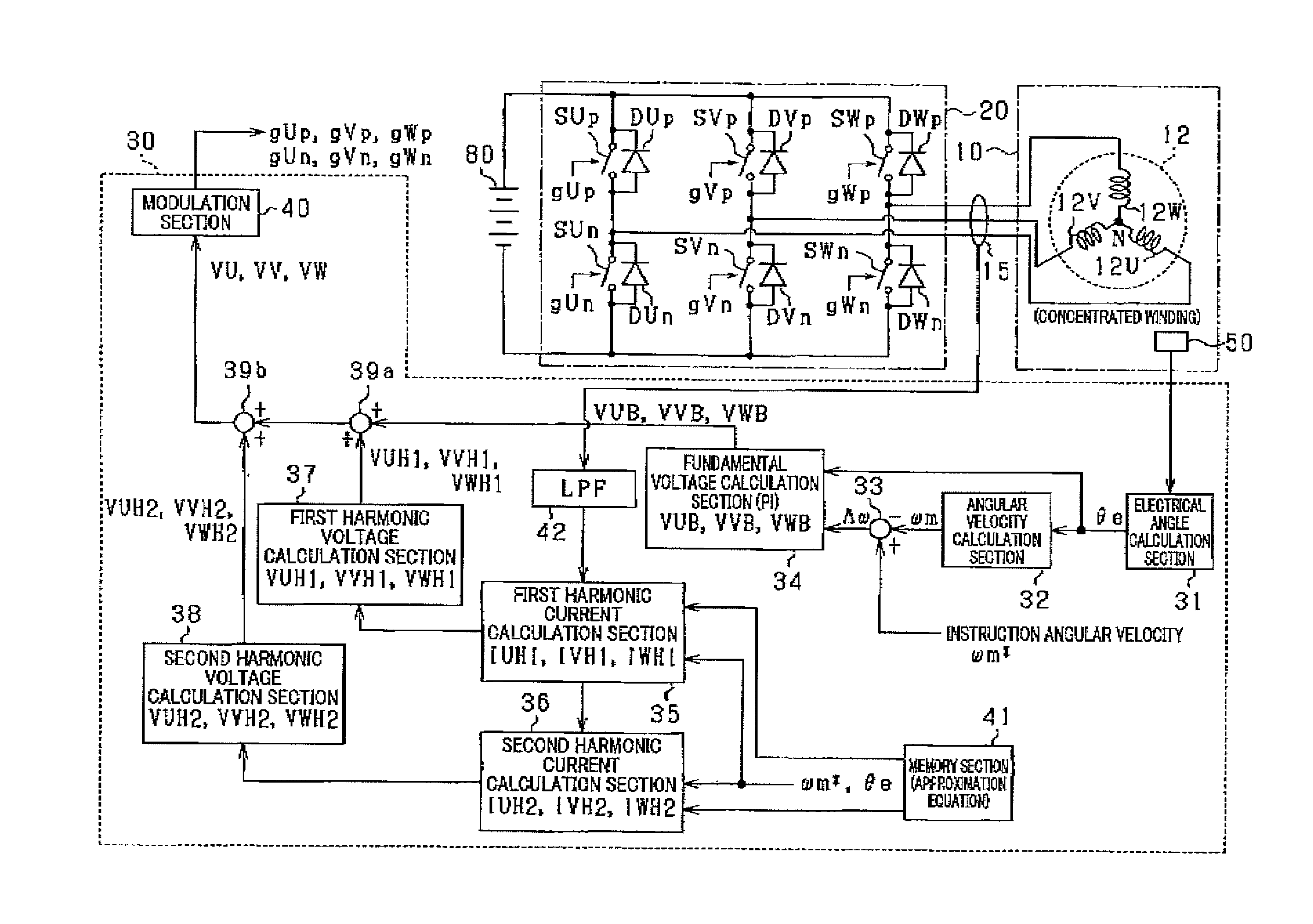
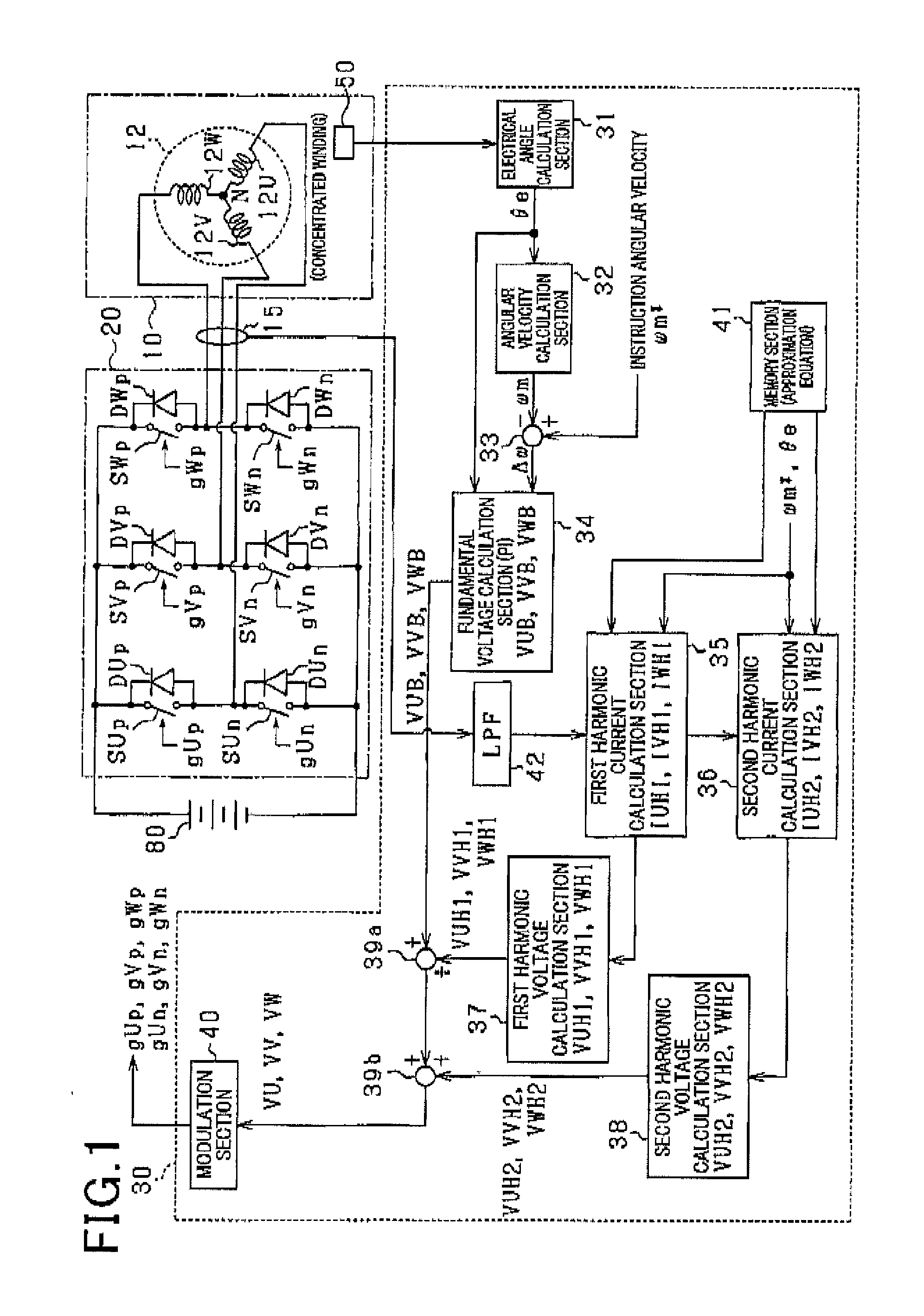
[0044]A description will be given of the control device 30 for a rotating electric machine according to the first exemplary embodiment with reference to FIG. 1 to FIG. 7.

[0045]FIG. 1 is a view showing a schematic structure of a rotating electric machine system (or the motor system) having the control device 30 according to the first exemplary embodiment. The motor system shown in FIG. 1 is the in-vehicle A / C system. The in-vehicle A / C system has the control device 30, the blower motor 10 (hereinafter, the motor 10) as a rotating electric machine, an inverter 20, a current sensor 15 and a rotation angle sensor 50.

[0046]The motor 10 is a permanent magnet synchronous motor of three phase concentrated windings (hereinafter, three phase windings). The inverter 20 receives and converts a direct current electric power (DC electric power) supplied from a battery 80 as a direct current power source to an alternating current electric power (AC electric power). The motor 10 rotates when receiv...

second exemplary embodiment

[0131]A description will be given of the control device 30 according to the second exemplary embodiment with reference to FIG. 8 to FIG. 10.

[0132]As previously described, the first exemplary embodiment uses the suppression range of electromagnetic force from L-th order to (N−2)-th order which is larger than L-th order, and odd numbered harmonic currents within the suppression range of L-th order to N-th order are superimposed over the fundamental current, and these order electromagnetic force components are converted to the N-th electromagnetic force component. In particular, the first exemplary embodiment uses the (6M−2)-th electromagnetic force component and the 6M-th electromagnetic force component within the suppression range, and the (6M−1)-th harmonic current and the (6M+1)-th electromagnetic force component are superimposed over the fundamental current in order to convert the electromagnetic force within the suppression range to the (6M+2)-th electromagnetic force component.

[...

third exemplary embodiment

[0149]A description will be given of the control device 30A according to the third exemplary embodiment with reference to FIG. 11 to FIG. 16.

[0150]The control device 30A according to the third exemplary embodiment performs a method of calculating harmonic currents to be superimposed over the fundamental current, which is different from the method performed by the control device 30 according to the first exemplary embodiment previously described. That is, the control device 30A uses the suppression range including the (6M−2)-th electromagnetic force component and the 6M-th electromagnetic force component. The control device 30A superimposes the (6M−1)-th harmonic current and the (6M+1)-th harmonic current over the fundamental current.

[0151]In particular, the third exemplary embodiment will explain the case of M=2. The control device 30A uses the eleventh harmonic current as the primary harmonic currents IHU1, IHV1 and IHW1, and the twelfth harmonic current as the secondary harmonic c...


PUM


Abstract

A control device capable of suppressing electromagnetic force applied to a motor has a harmonic current calculation section and an operation section. The harmonic current calculation section calculates amplitude and phase of each of harmonic currents to be superimposed over a fundamental current which flows in phase windings of a stator of the motor based on conditions relating to load change of the motor. The operation section generates and transmits instruction signals to an inverter so that the calculated superimposed harmonic currents flow in the phase windings of the stator.

Description

CROSS-REFERENCE TO RELATED APPLICATION[0001]This application is related to and claims priority from Japanese Patent Applications No. 2015-102664 filed on May 20, 2015, and No. 2016-001799 filed on Jan. 7, 2016, the contents of which are hereby incorporated by reference.BACKGROUND OF THE INVENTION[0002]1. Field of the Invention[0003]The present invention relates to control devices for rotating electric machines.[0004]2. Description of the Related Art[0005]There has been proposed a control device for rotating electric machines capable of reducing noise or radiated noise in a rotating electric machine generated during the rotation of the rotating electric machine. Such conventional control devices suppress electromagnetic force induced in the radial direction of the rotating electric machine in order to reduce radiated noise.[0006]Patent document 1 discloses such a conventional control device for rotating electric machines. The control device disclosed in patent document 1 is applied t...

Claims


Application Information

Patent Timeline
Patent Type & Authority Applications(United States)
IPC IPC(8): H02P6/10
CPCH02P6/10F04D25/0606H02P29/50H02P6/06H02P6/14H02P2209/07
Inventor AKIMATSU, RYUNOSUKETONARI, TATSUYAUCHIDA, TOSHIHIRO
Owner DENSO CORP
Why Eureka
Try Eureka