Method in pneumatic material conveying system and a pneumatic material conveying system

a conveying system and material technology, applied in the field of pneumatic material conveying system, can solve the problems of high air flow in the piping, noise, dust and fine particles in the outlet pipe, and achieve the effect of reducing the volume of outlet air, reducing the noise effect caused by the operation of the system, and effectively arranging the conveying of materials

Inactive Publication Date: 2010-11-04
MARICAP OY
View PDF18 Cites 6 Cited by
  • Summary
  • Abstract
  • Description
  • Claims
  • Application Information

AI Technical Summary

Benefits of technology

[0011]The arrangement according to the invention has numerous significant advantages. By opening and closing the feed points of the system according to the invention, the material is provided with an effective transfer into and conveyance in the conveying pipe when, at the same time, the noise effect caused by the operation of the system can be minimised. By arranging the conveying pipe of the material conveying system to consist of operating areas i.e. partial circuits, it is possible to effectively arrange the conveyance of the material in the conveying piping and emptying the feed points into the conveying pipe. By arranging the piping of the system to comprise a circuit where at least part of conveying air circulates, the volume of outlet air can be decreased. At the same time, the energy consumption of the system is minimised. By maintaining underpressure and simultaneously blowing, it is possible to provide an effective circulation of conveying air in the circuit and conveyance of material in the conveying pipe. With the arrangement according to the invention, it is possible to decrease the volume of outlet air substantially and simultaneously to decrease possible problems with dust and fine particles in the outlet pipe. The arrangement according to the invention also substantially decreases the noise problem caused by prior art. Moisture accumulated in the piping is minimised and the piping can be dried by circulating air in the piping. As the volume of air being sucked inside decreases, also energy consumption decreases.

Problems solved by technology

The vacuum conveying systems typically contain, inter alia, the following problems: high energy consumption, high air flow in the piping, problems with noise, dust and fine particles in the outlet pipe.

Method used


Image

  • Method in pneumatic material conveying system and a pneumatic material conveying system
  • Method in pneumatic material conveying system and a pneumatic material conveying system
  • Method in pneumatic material conveying system and a pneumatic material conveying system

Examples


Embodiment Construction

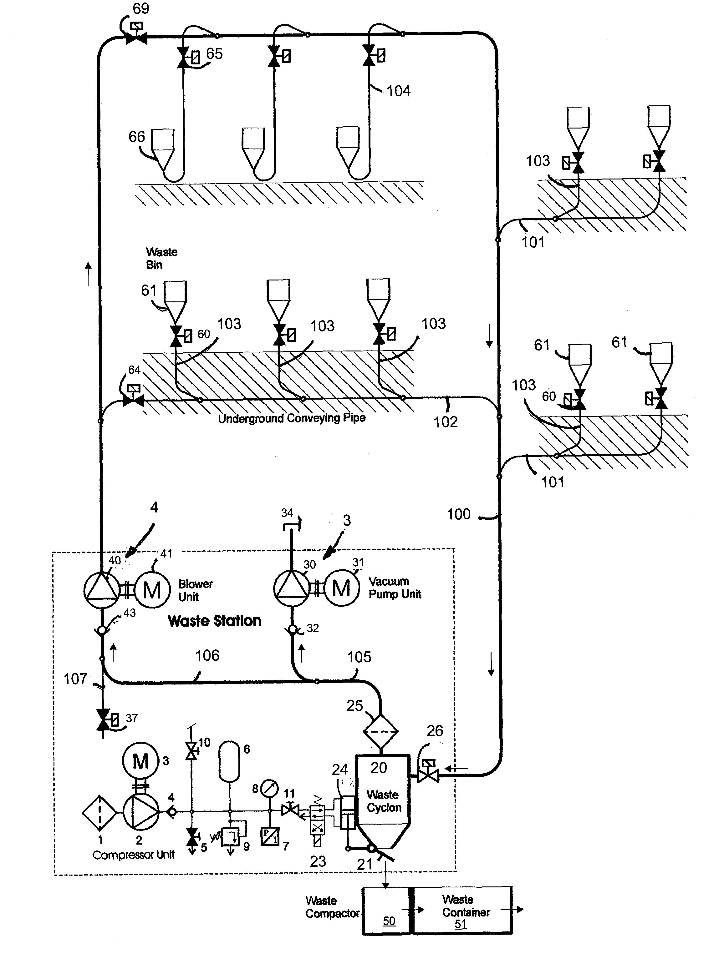
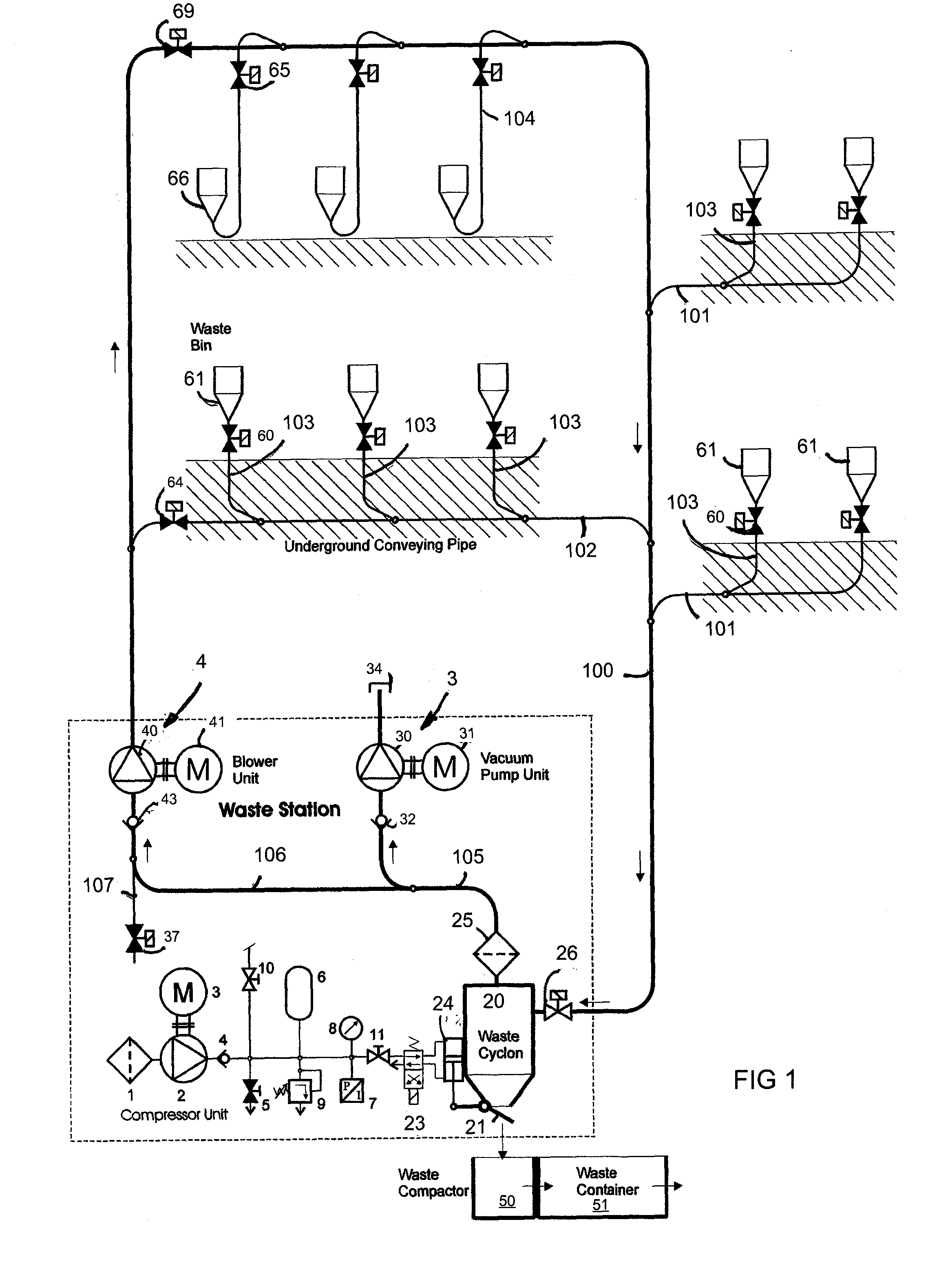
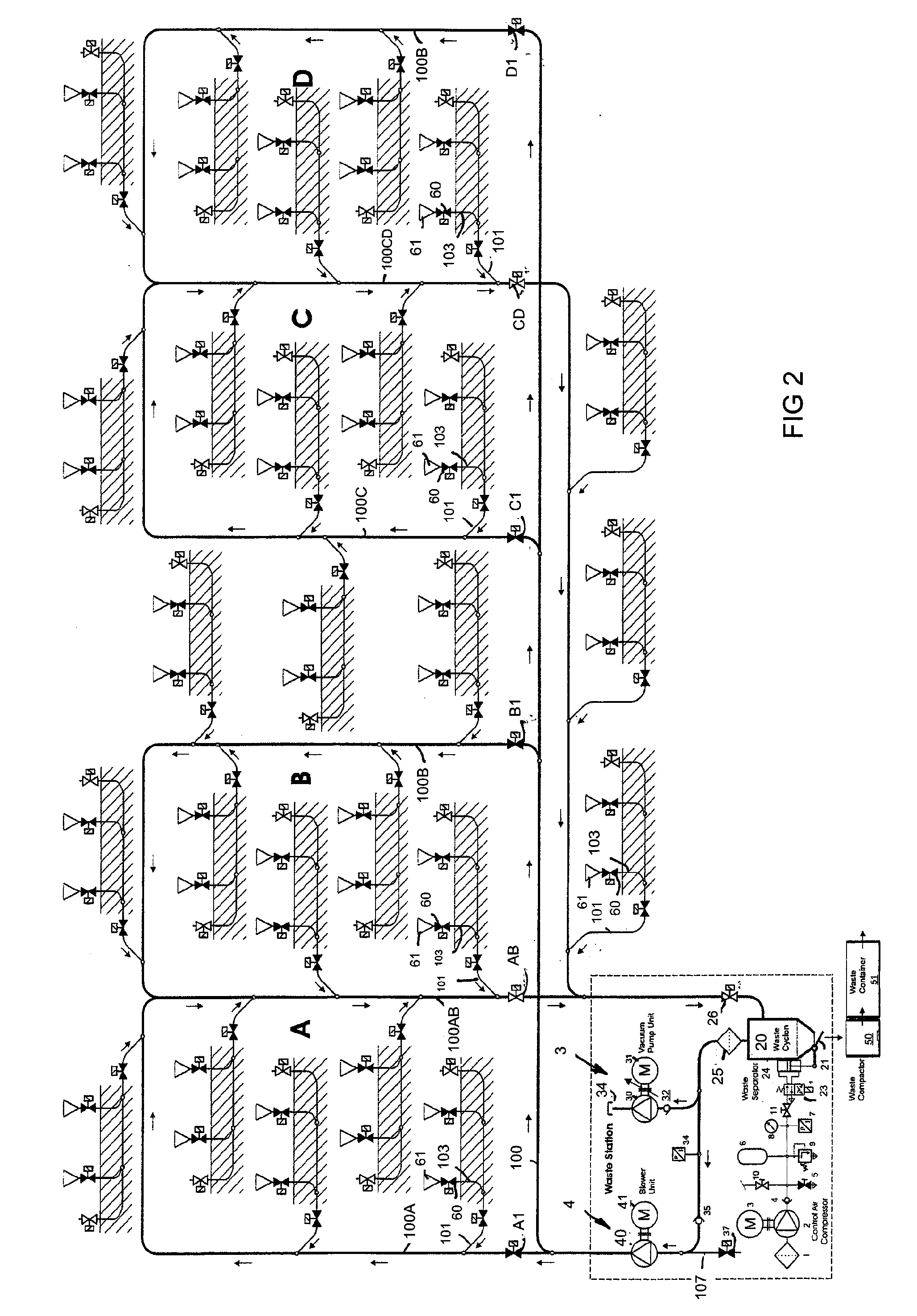
[0016]FIG. 1 schematically shows a pneumatic material conveying system, particularly a waste material conveying system. FIGS. 1 and 2 shows the underlying basic principles of the material conveying system of the invention and FIG. 3 shows an embodiment of the invention.

[0017]In FIG. 1, reference number 61, 66 designates a feed station of materials, particularly of waste material, intended to be conveyed, from which station material, particularly waste material, such as household waste, intended to be conveyed is fed to the conveying system. The system can comprise several feed stations 61, 66 from which the material intended to be conveyed is fed to a conveying piping 100, 101, 102, 103, 104. Typically, the conveying piping comprises a main conveying pipe 100 into which several branch conveying pipes 101, 102 can have been connected and into which again several feed stations 61, 66 can have been connected via feed pipes 103, 104. The fed material is conveyed along the conveying pipi...


PUM


Abstract

A method for feeding and conveying material in a pneumatic material conveying system, such as a waste conveying system, which conveying system comprises at least one feed point (61) of material, particularly of waste material, a material conveying pipe (100) which is connectable to the feed point (61), a separator device (20) in which the material being conveyed is separated from conveying air, and means (3, 4) for providing a pressure difference in the conveying pipe (100) at least during the conveyance of the material. Underpressure is provided in the conveying pipe (100) at least at the point of the feed point (61) intended to be emptied, the feed points are emptied to the conveying pipe (100) using an emptying sequence in which first is emptied a feed point located closer to the separator device (20) in the material conveying direction and next a feed point (61) located substantially farther from the separator device (20) in the material conveying direction.

Description

BACKGROUND OF INVENTION[0001]The invention relates to a method according to the preamble of claim 1.[0002]The invention also relates to a method according to claim 2.[0003]The invention further relates to a pneumatic material conveying system according to claim 17.[0004]The invention relates generally to pneumatic conveying systems, such as vacuum conveying systems, particularly to collecting and conveying waste, such as conveying household waste.[0005]Systems are known in which waste is conveyed in a piping by means of suction. In these, waste is conveyed for long distances in the piping by suction. Apparatuses are utilised, inter alia, for conveying waste in different institutions. Typical for them is that a vacuum apparatus is used for achieving a pressure difference, in which apparatus underpressure in the conveying pipe is provided with vacuum generators, such as vacuum pumps or an ejector apparatus. In the conveying pipe, there is typically at least one valve element by openin...

Claims


Application Information

Patent Timeline
Patent Type & Authority Applications(United States)
IPC IPC(8): B65G53/34
CPCB65G53/24B65F5/005B65G53/34B65G53/521B65G53/32
Inventor SUNDHOLM, GORAN
Owner MARICAP OY
Why Eureka
Try Eureka