Blade for Windmill, Windmill and Wind Power Generator

a wind power generator and blade technology, applied in vessel construction, renewable energy generation, greenhouse gas reduction, etc., can solve the problems of speed decline, speed decrease, speed decrease, etc., and achieve the effect of less influence, less influence, and more effective rotation

Active Publication Date: 2009-07-02
ECO TECH CO
View PDF11 Cites 30 Cited by
  • Summary
  • Abstract
  • Description
  • Claims
  • Application Information

AI Technical Summary

Benefits of technology

[0043]According to a blade for a windmill and a windmill of the present invention, a vertical rotation type windmill having less influence by wind directions can rotate more effectively.
[0044]

Problems solved by technology

Horizontal rotation axis type windmills have an advantage of having a greater collection rate of wind energy than that of vertical rotation axis type windmills, however the rotation efficiency decreases unless the rotation axis and blades are opposed to the wind direction, and especially they have disadvantages of speed decrease occurred by difference of the wind direction due to elevation difference between the upper and low

Method used


Image

  • Blade for Windmill, Windmill and Wind Power Generator
  • Blade for Windmill, Windmill and Wind Power Generator
  • Blade for Windmill, Windmill and Wind Power Generator

Examples


Embodiment Construction

[0062]Hereinafter, referring to the drawings, embodiments of blades for a windmill, a windmill and wind power generator of the present invention will be explained.

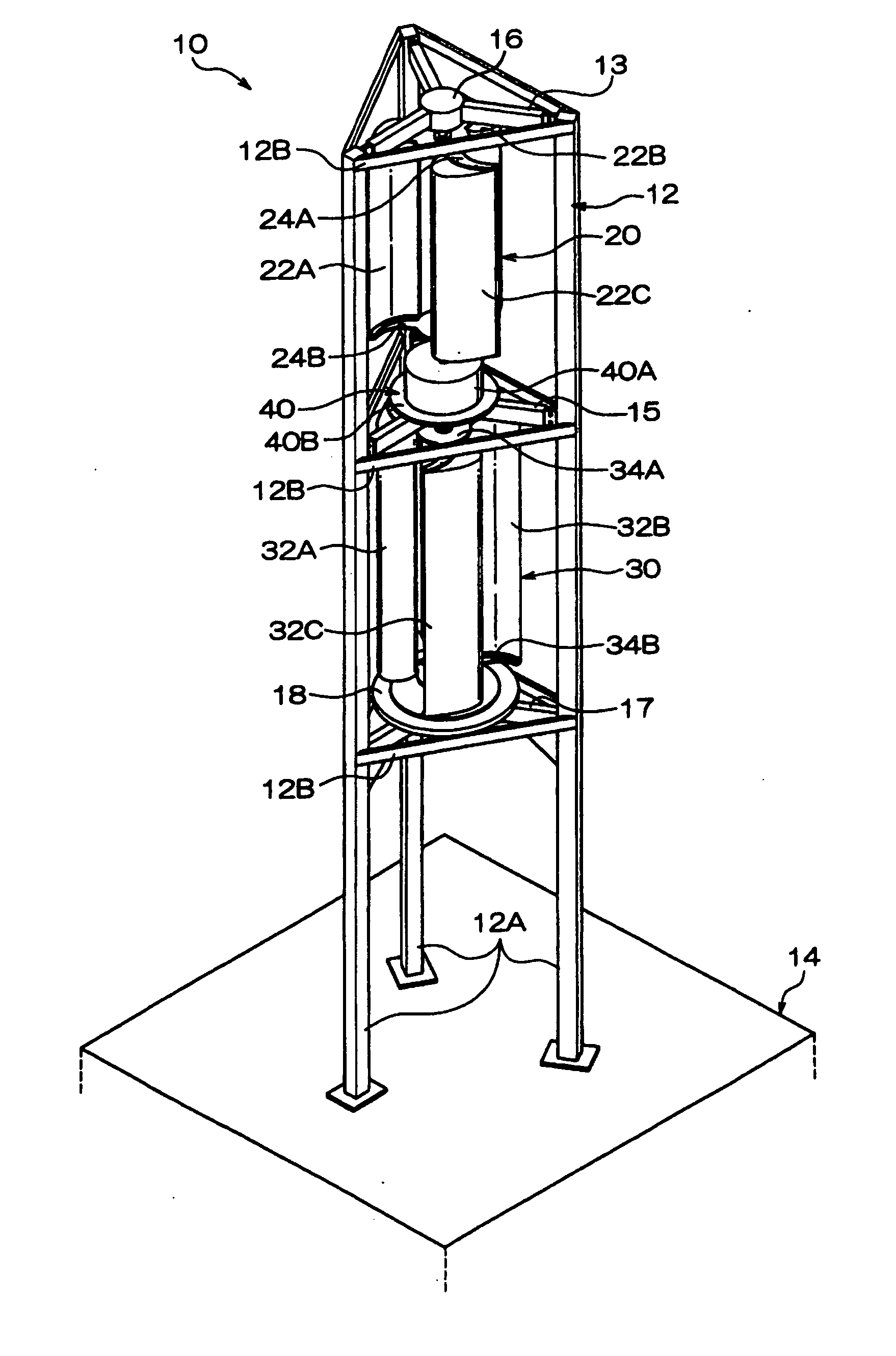
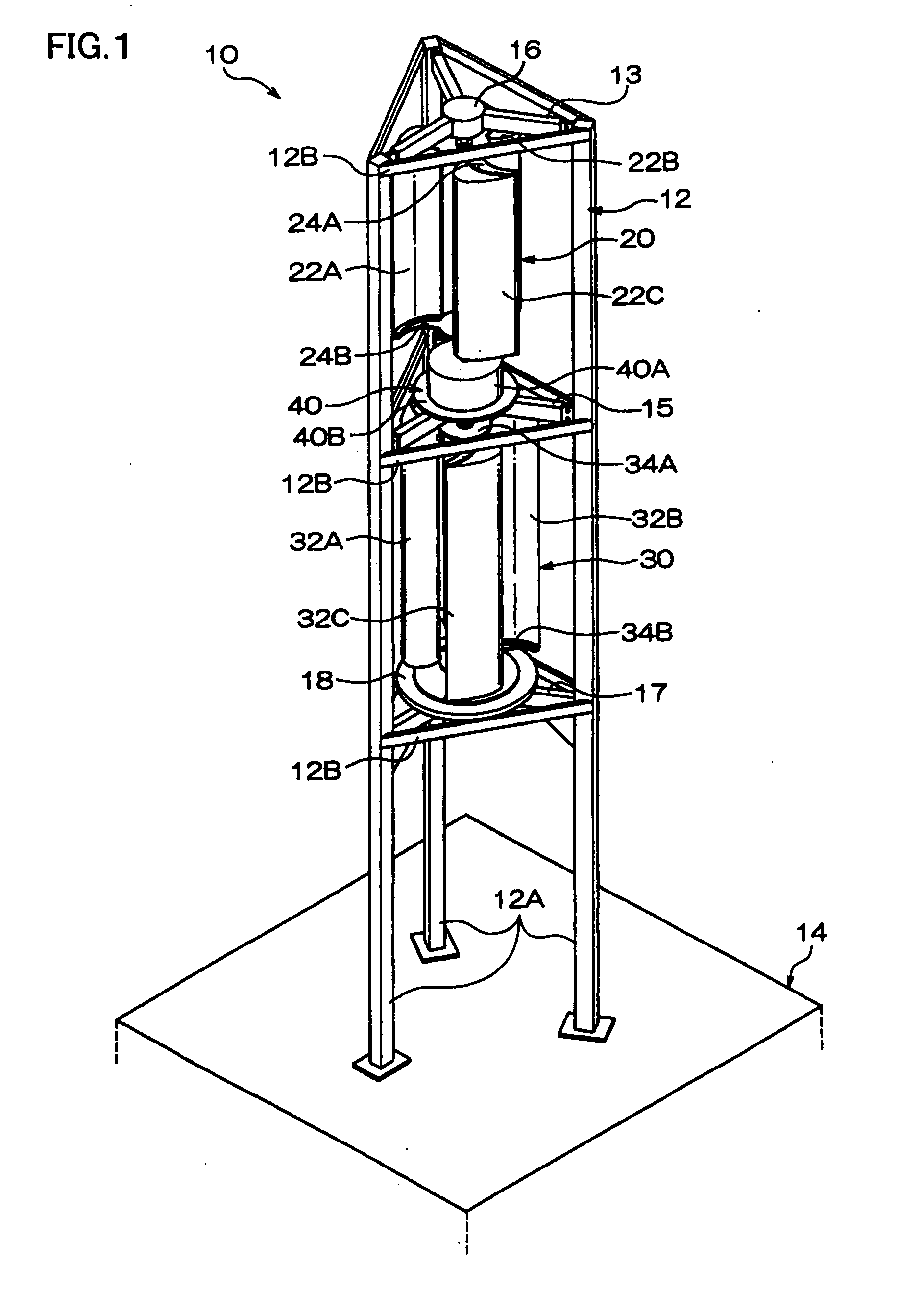
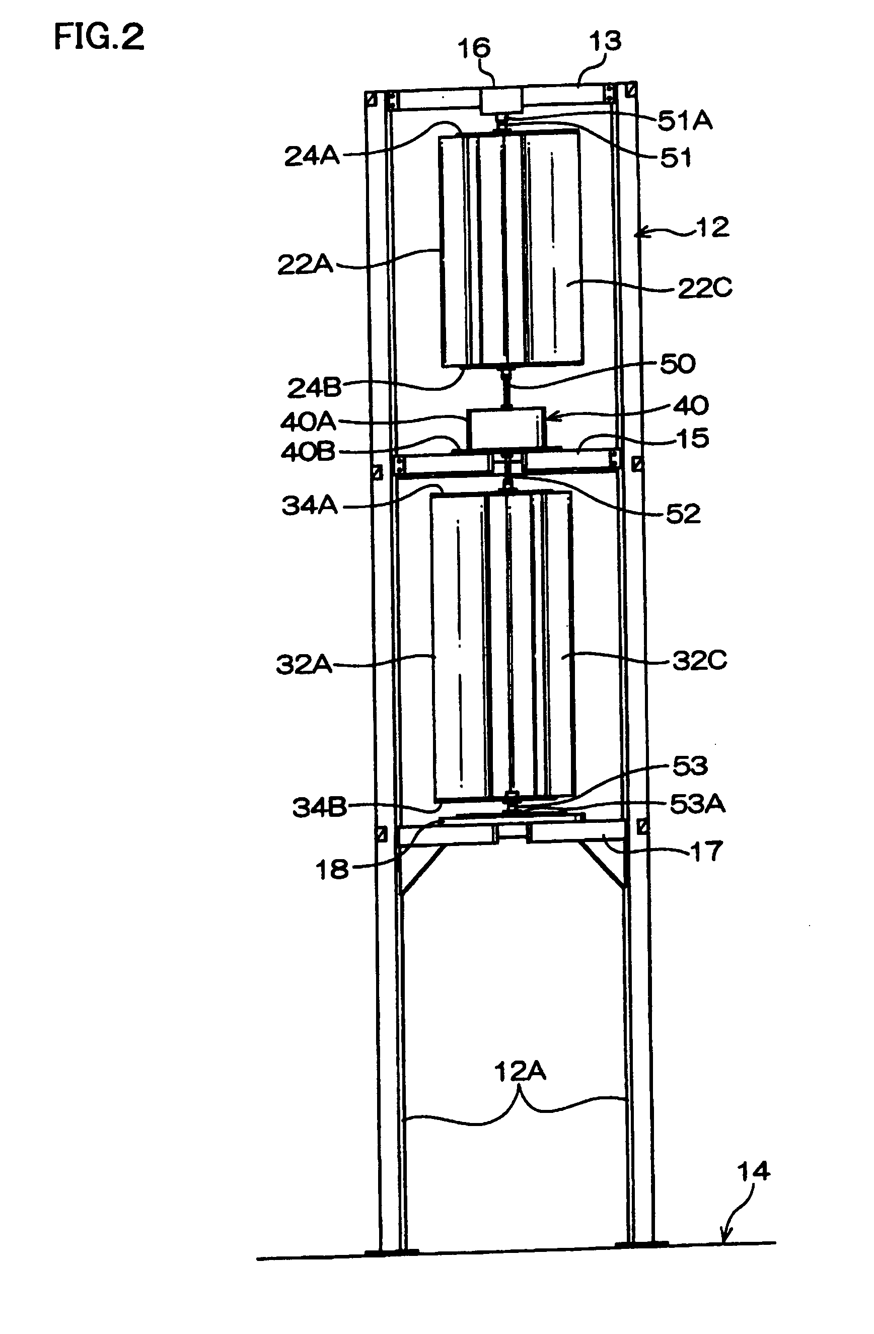
[0063]As shown in FIGS. 1 to 3, a wind power generator 10 comprises a frame 12, a first windmill 20, a second windmill 30 and a power generating device 40.

[0064]The frame 12 comprises three columns 12A provided protrudingly in a vertical direction on a base 14 and a plurality of beams 12B connecting between the respective columns 12A. The three columns 12A are disposed, as viewed from a vertical direction, at apex positions of a substantially equilateral triangle, and the beams 12B connect the respective columns 12A at three height positions including a top end portion of the columns 12A. The three beams 12B at each height position configure an equilateral triangle shape.

[0065]A first windmill 20 and a second windmill 30 are so-called vertical side windmills, as shown in FIG. 3, having a common rotation center M disposed i...


PUM


Abstract

A blade for a windmill disposed around a rotation center (M) in a vertical direction so as to receive wind force, comprising a front surface (26) including;
    • a front nose surface (26F) being disposed at front of a traveling direction, also having a greatest average curvature
    • a low speed airflow passing surface (26L) disposed on a closer side to the rotation center, and formed continuously from the front nose surface to rearward of the traveling direction, and
    • a high speed airflow passing surface (26H) disposed a distant side from the rotation center, formed continuously from the front nose surface to rearward of the traveling direction with a curved surface swollen greater than the low speed airflow passing surface, and having length as viewed from the vertical direction greater than the low speed airflow passing surface.

Description

RELATED APPLICATION[0001]This application is a National Stage entry of International Application No. PCT / JP2006 / 311128, filed on Jun. 2, 2006, the entire specification claims and drawings of which are incorporated herewith by reference.BACKGROUND OF THE INVENTION[0002]1. Field of the Invention[0003]This invention relates to a blade for a windmill, a windmill and a wind power generator, and especially a vertical type windmill, a blade for a windmill used for this windmill and a wind power generator using the vertical type windmill.[0004]2. Background of the Art[0005]There are vertical rotation axis type and horizontal rotation axis type windmills, and nowadays horizontal rotation type ones are mainly used for wind power generation. Horizontal rotation axis type windmills have an advantage of having a greater collection rate of wind energy than that of vertical rotation axis type windmills, however the rotation efficiency decreases unless the rotation axis and blades are opposed to th...

Claims


Application Information

Patent Timeline
IPC IPC(8): F03D9/00F03D3/02F03D3/06
CPCF03D3/02F03D3/061Y02E10/74F05B2240/211F05B2240/301F03D9/002F03D9/25
Inventor KATO, MASAHARU
Owner ECO TECH CO
Why Eureka
Try Eureka